00196845-02_AI_Vakuumpumpe_SXDX4_X-Serie-S_de_en - 第106页
Fitting the Vacuum Pump Changeover 3.2.17 Fitting the Cooling Plate with Fan 106 Vacuum Pump Vakuumpumpe 3.2.17 3 . 2 . 1 7 F it t in g t h e C o o lin g P la t e w it h F a n Fitting the Cooling Plate with Fan 3.2.18 3 …
Fitting the Vacuum Pump
3.2.16 Checking the Direction of Pump and Fan Operation Changeover
Vacuum Pump Vakuumpumpe 105
► Fit the filter back into place.
► Close the installation location with the cooling plate (see "3.2.17 Fitting the Cooling Plate with Fan"
[ ➙ 106]).
► Check the connections for air-tightness. Make sure that they are not sucking in air incorrectly.
3.2.16.2
3.2.16.2 Check the Direction of Fan Operation
Check the Direction of Fan Operation
► Switch the placement machine on at the main switch. The vacuum pump must also switch itself on,
although this might not occur immediately after the machine is switched on.
► Start the vacuum pump (see "3.2.16.1 Checking the Direction of Pump Operation" [ ➙ 104]).
► Check the direction of fan operation. The fan must blow air into the machine.
If the fan is running incorrectly, turn the 24 Volt in the Mini Mad BN Lock connection.
► Switch the machine on at the main switch. The vacu-
um pump must also switch itself on, although this
might not occur immediately after the machine is
switched on.
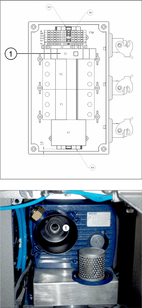
► Start the vacuum pump with the S1 button (1) on the
connection unit. The button can be reached through
an opening in the housing.
► Hold a hand or sheet of paper in front of the opening
of the pump through which air is sucked in (1).
⇨ The pump must be sucking air in!
► If the pump is running in the wrong direction, discon-
nect the entire system from the voltage supply. Un-
plug the vacuum pump from the power.
► If both connections for the vacuum pump show the
same effect, rewire the network cable connection in
the connection unit (exchange the phases).
► If only one vacuum pump is running incorrectly, re-
wire at the relevant fuse (exchange the phases).
F1: Pump 1
F2: Pump 2
Fitting the Vacuum Pump
Changeover 3.2.17 Fitting the Cooling Plate with Fan
106 Vacuum Pump Vakuumpumpe
3.2.17
3.2.17 Fitting the Cooling Plate with Fan
Fitting the Cooling Plate with Fan
3.2.18
3.2.18 Fitting the Connection Unit
Fitting the Connection Unit
NOTICE
Checking the direction of pump operation
Check the direction of pump operation before you close the installation location with the cooling
plate (see "3.2.16.1 Checking the Direction of Pump Operation" [ ➙ 104]).
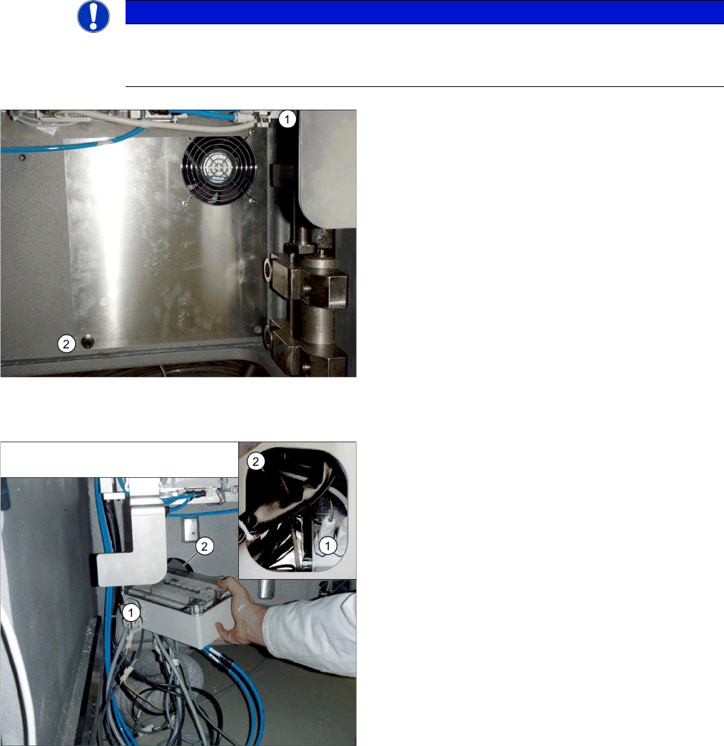
► Connect the fan cable to the "connection unit assem-
bly" (see also "3.2.9 Running the Supply Cable"
[➙98]).
► Position the top fixture hole on the cooling plate onto
the M10 screw previously inserted (1) and secure this
with a washer and nut.
► Secure the cooling plate with an M4 screw (2), insert-
ed from the front.
► Perform a fan function test (see "3.2.16.2 Check the
Direction of Fan Operation" [ ➙ 105]).
➢ If the direction of running is correct for both the pump
and fan, you can fit the "connection unit assembly"
into its installation point in the machine base.
► Unplug all connections from the connection unit (1).
► Slightly turn the connection unit to fit it through the
opening in the machine base (2).
► Restore all connections.

Fitting the Vacuum Pump
3.2.19 Setting the motor protection switch Changeover
Vacuum Pump Vakuumpumpe 107
3.2.19
3.2.19 Setting the motor protection switch
Setting the motor protection switch
The correct values for setting the motor circuit breaker can be found in section "5.6.1 Replacing the Mo-
tor Circuit Breaker with Motor Protection Tripping Unit" [ ➙ 125].
3.2.20
3.2.20 Conversion for C&P20a
Conversion for C&P20a
▪ Conversion kit for vacuum pump operation C&P20 [00119790-xx]
Original state - C&P20 A for compressed air operation
NOTICE
Restrictions for TwinHead or CPP head on the gantry to be converted
The TwinHead and CPP placement heads are not compatible with vacuum pump operation. Do
not convert the pneumatic supply for the gantry affected to vacuum mode. If the compressed
air supply for this head is converted to vacuum operation, the return cylinder will be unable to
move out and the Z axis will remain in its top position.
CAUTION
Conversion from C&P20A head to TwinHead or CPP head
If you need to convert a gantry from C&P20A to TwinHead or CPP head, you must re-establish
the original compressed air supply for this gantry. Conversion reversal must be performed on
all assemblies for this gantry. Partial conversion of the pneumatic unit, for example, involving
disconnection of the gantry hoses (additional vacuum hoses) during compressed air opera-
tions, can lead to serious placement machine malfunctions.
CAUTION
Conversion from TwinHead to C&P20A head with vacuum operation
If you need to convert a gantry with TwinHead to C&P20A head with vacuum function, you must
retrofit the vacuum equipment for this gantry. If you operate a C&P20A head which has been
converted for vacuum operation at a gantry with compressed air, this could lead to serious dam-
age to the placement head if the silicon hoses to the segments should loosen.
CAUTION
Preparatory work
After you have properly shut-down the operating system: turn the machine off at the main
switch and isolate it from the mains, before you perform any work to the machine. In addition,
the compressed air supply must be turned off at the main valve of the compressed air unit, in
the machine base, and the compressed air lines must be bled by actuating the needle valve on
the compressed air unit. See also "1.2 Preparatory Work..." [ ➙ 72].