00196845-02_AI_Vakuumpumpe_SXDX4_X-Serie-S_de_en - 第108页
Fitting the Vacuum Pump Changeover 3.2.20 Conversion for C&P20a 108 Vacuum Pump Vakuumpumpe 3.2.20.1 3 . 2 . 2 0 . 1 R e m o v in g t h e S ile n c e r Removing the Silencer 3.2.20.2 3 . 2 . 2 0 . 2 R e m o v in g t …

Fitting the Vacuum Pump
3.2.19 Setting the motor protection switch Changeover
Vacuum Pump Vakuumpumpe 107
3.2.19
3.2.19 Setting the motor protection switch
Setting the motor protection switch
The correct values for setting the motor circuit breaker can be found in section "5.6.1 Replacing the Mo-
tor Circuit Breaker with Motor Protection Tripping Unit" [ ➙ 125].
3.2.20
3.2.20 Conversion for C&P20a
Conversion for C&P20a
▪ Conversion kit for vacuum pump operation C&P20 [00119790-xx]
Original state - C&P20 A for compressed air operation
NOTICE
Restrictions for TwinHead or CPP head on the gantry to be converted
The TwinHead and CPP placement heads are not compatible with vacuum pump operation. Do
not convert the pneumatic supply for the gantry affected to vacuum mode. If the compressed
air supply for this head is converted to vacuum operation, the return cylinder will be unable to
move out and the Z axis will remain in its top position.
CAUTION
Conversion from C&P20A head to TwinHead or CPP head
If you need to convert a gantry from C&P20A to TwinHead or CPP head, you must re-establish
the original compressed air supply for this gantry. Conversion reversal must be performed on
all assemblies for this gantry. Partial conversion of the pneumatic unit, for example, involving
disconnection of the gantry hoses (additional vacuum hoses) during compressed air opera-
tions, can lead to serious placement machine malfunctions.
CAUTION
Conversion from TwinHead to C&P20A head with vacuum operation
If you need to convert a gantry with TwinHead to C&P20A head with vacuum function, you must
retrofit the vacuum equipment for this gantry. If you operate a C&P20A head which has been
converted for vacuum operation at a gantry with compressed air, this could lead to serious dam-
age to the placement head if the silicon hoses to the segments should loosen.
CAUTION
Preparatory work
After you have properly shut-down the operating system: turn the machine off at the main
switch and isolate it from the mains, before you perform any work to the machine. In addition,
the compressed air supply must be turned off at the main valve of the compressed air unit, in
the machine base, and the compressed air lines must be bled by actuating the needle valve on
the compressed air unit. See also "1.2 Preparatory Work..." [ ➙ 72].
Fitting the Vacuum Pump
Changeover 3.2.20 Conversion for C&P20a
108 Vacuum Pump Vakuumpumpe
3.2.20.1
3.2.20.1 Removing the Silencer
Removing the Silencer
3.2.20.2
3.2.20.2 Removing the Vacuum Unit Holding Circuit C&P20A
Removing the Vacuum Unit Holding Circuit C&P20A
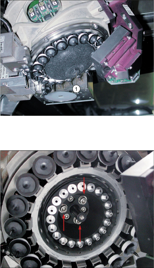
C&P20A with porous silencer for compressed air
► Make sure that you do not damage or contaminate
the camera lens system.
► Loosen the screw (1) fastening the silencer.
► Carefully lever out the silencer.
► Make sure that you do not damage the DP drives.
C&P20A with vacuum unit holding circuit
► Unscrew the three screws and remove the vacuum
unit holding circuit for the C&P20.
Fitting the Vacuum Pump
3.2.20 Conversion for C&P20a Changeover
Vacuum Pump Vakuumpumpe 109
3.2.20.3
3.2.20.3 Fitting the Aperture Ring and Vacuum Cover
Fitting the Aperture Ring and Vacuum Cover
NOTICE
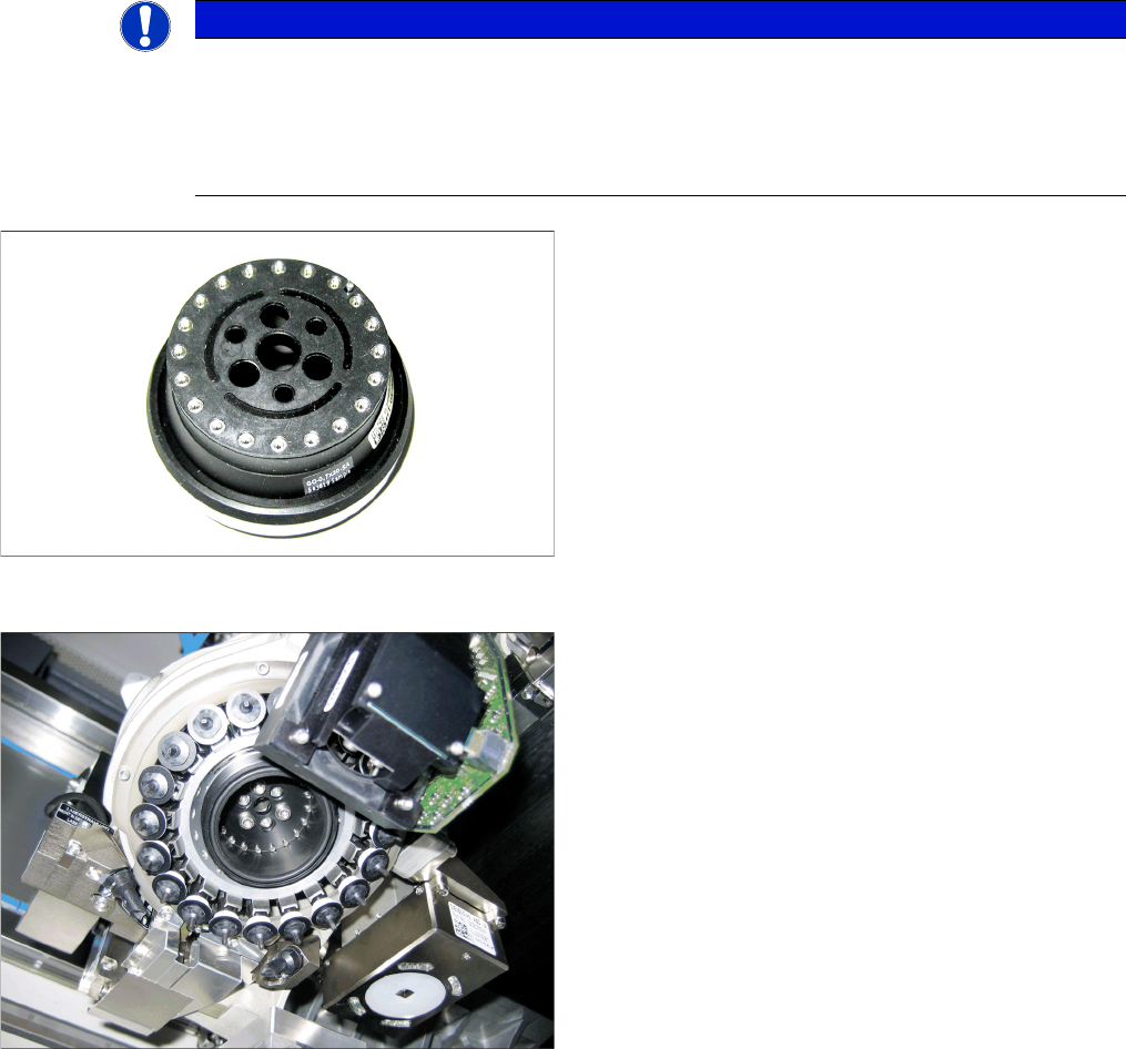
Aperture ring
Before inserting the aperture ring, make sure that the seal disk [03046345-xx] has been posi-
tioned correctly (orientation) on the aperture ring for the C&P20A [03046344-xx].
When inserting the new aperture ring for the C&P20A, make sure that the pin engages in the
relevant hole on the star carrier. The aperture ring should remain fixed from alone.
Aperture ring C&P20A with seal disk
► When tightening the screws, carefully take hold of the
star near the segment guidances and hold it on the
star carrier.
► Make sure you do not damage the aperture ring or
nozzles.
C&P20 A with aperture ring C&P20 A [03046344
-
xx]
► Screw the aperture ring tight using the DIN912-
M3x10 screws. Make sure that it is not distorted.
► Check whether the O-ring 42x2 NBR70 has been
properly placed into the groove on the aperture ring.