00196845-02_AI_Vakuumpumpe_SXDX4_X-Serie-S_de_en - 第111页
Fitting the Vacuum Pump 3.2.21 Final Work: Change over Vacuum Pump Vakuumpumpe 111 3.2.21.4 3 . 2 . 2 1 . 4 C h e c k in g t h e H o ld C ir c u it V a c u u m S y s t e m C & P 2 0 A f o r A ir - T ig h t n e s s Ch…
Fitting the Vacuum Pump
Changeover 3.2.21 Final Work:
110 Vacuum Pump Vakuumpumpe
3.2.21
3.2.21 Final Work:
Final Work:
3.2.21.1
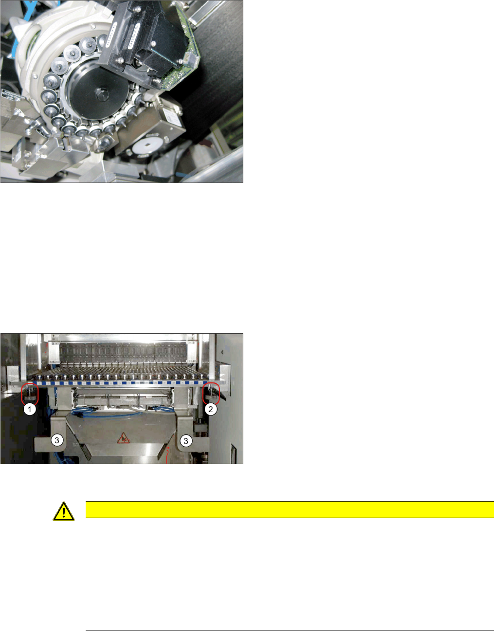
3.2.21.1 Docking the Component Trolley (SX Machines)
Docking the Component Trolley (SX Machines)
► Fit the empty tape duct and fix into place with four screws, inserted from below and attached to the
assembly brackets on the left and right.
► Dock the component trolleys into place.
3.2.21.2
3.2.21.2 Fitting the Manual Table (DX Machines)
Fitting the Manual Table (DX Machines)
3.2.21.3
3.2.21.3 Switching the Machine On
Switching the Machine On
► Open the compressed air shut-off valve.
► Close all doors.
► Switch the machine on at the main switch.
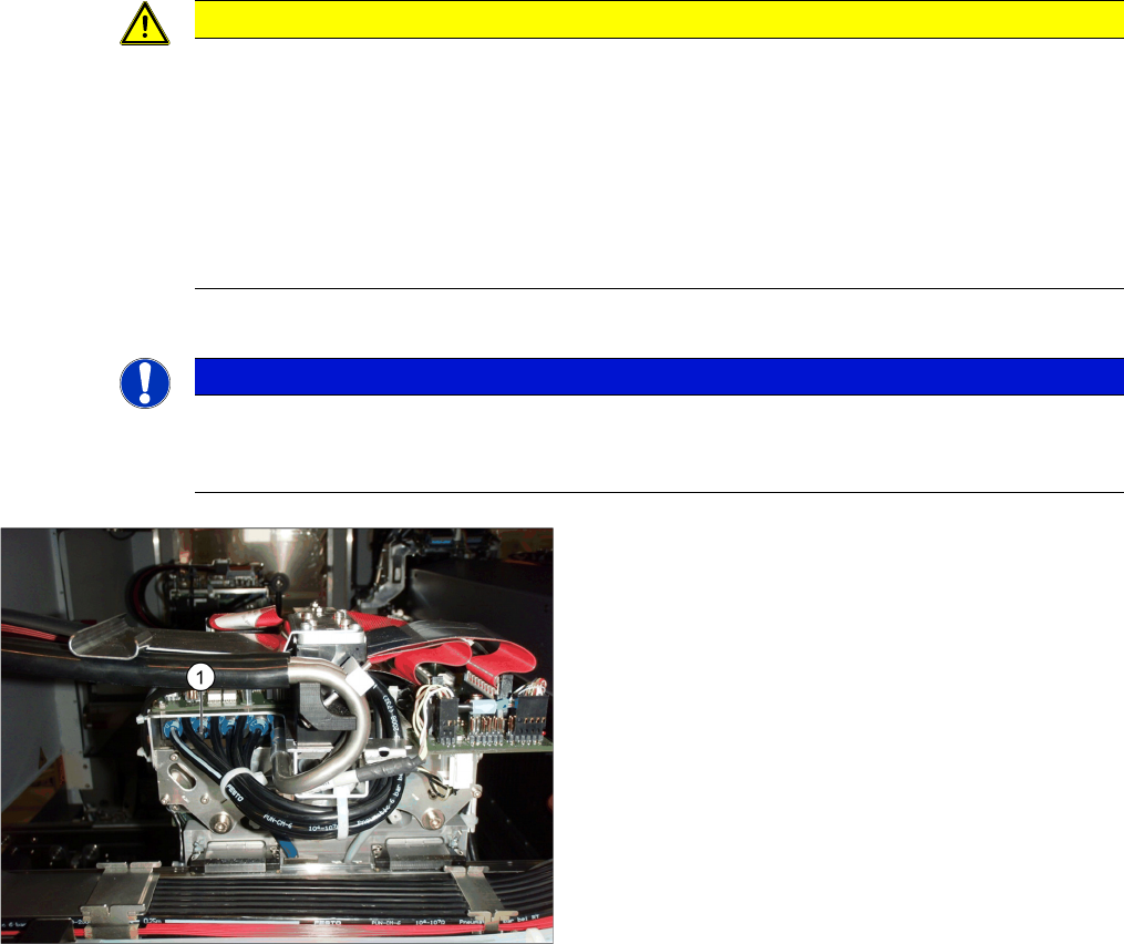
C&P20A with vacuum cover
► Screw the cover [03046347-xx] hand-tight onto the
aperture ring C&P20A.
► Fit the empty tape duct and fix into place with four
screws, inserted from below and attached to the as-
sembly brackets on the left and right (3).
► Insert the table into the machine and fix it into place
with the two knurled screws underneath the table (1
and 2).
► Insert the tape container and the reject tray.
CAUTION
Switch-on preconditions
Before switching on, perform the following checks to prevent injuries or serious damage to
property:
Make sure of the following before you switch the compressed air supply back on:
► Check that all hose connections are correctly assigned (also that there is no compressed
air in the vacuum hose).
► Check that all conditions for switch-on of the vacuum pump and connected placement ma-
chine have been fulfilled, as specified in the user guide.
Fitting the Vacuum Pump
3.2.21 Final Work: Changeover
Vacuum Pump Vakuumpumpe 111
3.2.21.4
3.2.21.4 Checking the Hold Circuit Vacuum System C&P20A for Air-Tightness
Checking the Hold Circuit Vacuum System C&P20A for Air-Tightness
Procedure
During the vacuum test, always measure at an open nozzle. In the case of large nozzles (1235), the
greater amount of escaping air usually makes the vacuum fall to values under -100 mbar. The reason
for this sharp drop – in the case of large nozzles nozzles without component – is the small reducing nipple
diameter in the reflecting ring, compared to the nozzle diameter.
With a component, vacuum values of -500 to -600 mbar are achieved.
If the above mentioned values are not achieved, the cause is usually a hose in the head area which has
not been properly pushed on as far as the end stop. Proceed as follows:
► Use the hose pliers to push all hoses on properly.
► Repeat the vacuum measurement.
Checking the overall function of the hold circuit vacuum system C&P20A
A vacuum test can be used to check the complete function of the vacuum system, as in the Venturi prin-
ciple.
The vacuum sensor in the hold circuit is only used to check whether the small nozzles in the reflecting
ring are free of dirt.
CAUTION
Minimum vacuum
At each placement machine/head there should be – depending on the nozzle configuration – a
vacuum of at least -500 mbar (for very large nozzles 1235) and
-600 mbar (for very small nozzles 1006) present!
The measurement is performed at a nozzle, using an external device, which corresponds to a
closed nozzle (with component).
During operation, do not undershoot a vacuum of -400 mbar. If this still happens, please contact
your SIPLACE hotline.
NOTICE
Avoid offset errors
To avoid offset errors, it can be advisable to perform both measurements with the same meas-
uring device.
► Measure the vacuum with an external pressure
measuring device:
⇨ At a connection (1) for the "distributor placement
head vacuum" on the gantry
⇨ At an open nozzle in the hold circuit on the place-
ment head.
⇨ The pressure difference may only be 30-50 mbar! If it
exceeds this, the system is not air-tight.

Fitting the Vacuum Pump
Retrofit compressed air supply 3.2.21 Final Work:
112 Vacuum Pump Vakuumpumpe
3.3
3.3 Retrofit compressed air supply
Retrofit compressed air supply
NOTICE
Scheduled modification at the proportional controller (pressure control valve)
The scheduled modification is related to all machines where all heads are operated with vacu-
um pumps.
In future one of the two proportional controllers [03065425-xx] is inapplicable. The compressed-
air piping will be converted accordingly at this place for the placing/holding circuit.
► If the proportional controller is missing remount it in case of a retrofit to compressed air op-
eration.
⇨ More information in detail was not available at the copy deadline.