00196845-02_AI_Vakuumpumpe_SXDX4_X-Serie-S_de_en - 第116页
Maintenance Maintenance Tasks for C&P20/A/M Head 4.2.1 Checkin g/Replacing th e Vacuum-Conducting Parts 116 Vacuum Pump Vakuumpumpe 4.2 4 . 2 M a in t e n a n c e T a s k s f o r C & P 2 0 / A / M H e a d Mainten…
Maintenance
4.1.4 Performing Maintenance Tasks Maintenance Tasks for Vacuum Pump
Vacuum Pump Vakuumpumpe 115
4.1.4
4.1.4 Performing Maintenance Tasks
Performing Maintenance Tasks
SXDX4 X34iS
4.1.4.1
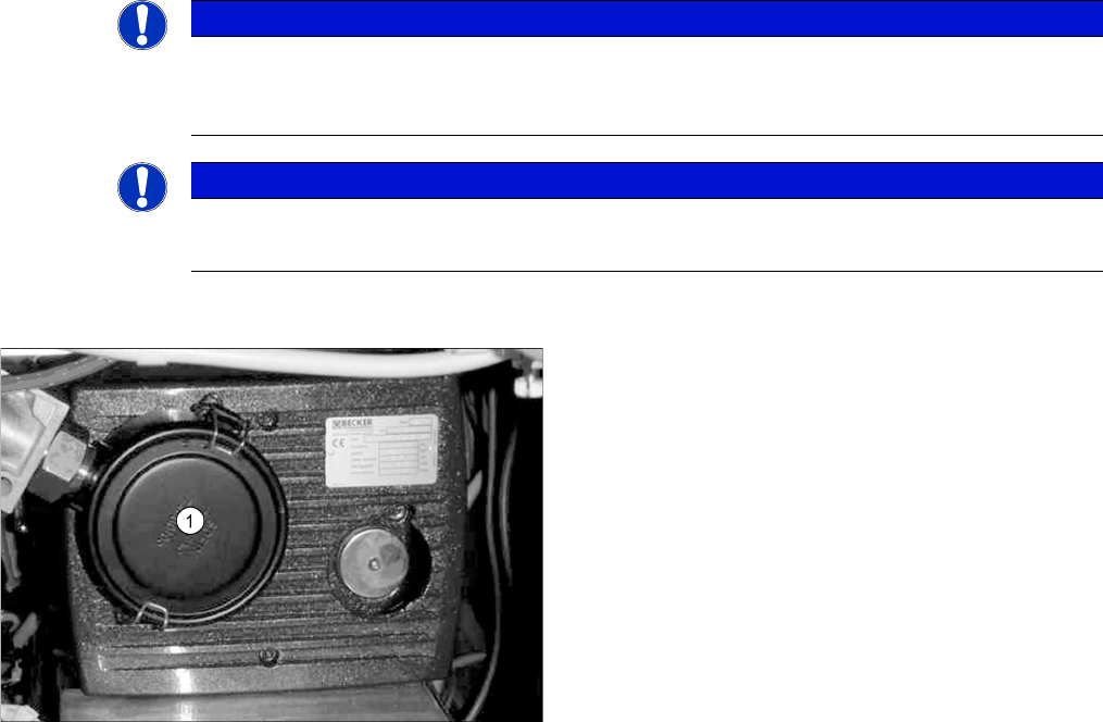
4.1.4.1 Checking/Replacing the Filter Insert
Checking/Replacing the Filter Insert
NOTICE
Observe the manufacturer's instructions
► For more information about maintenance intervals and about how to perform the individual
maintenance tasks, read the manufacturer's instructions for your vacuum pump.
NOTICE
Observe the assembly instructions
► Also read the "Assembly instructions for the vacuum pump SX4/DX4" [00196845-xx].
► Open the edgewise retaining clamp of the filter casing
(1) and remove the cap.
► Remove the vacuum filter.
► Check the vacuum filter and replace it if necessary
(filter insert [03077677-xx]).
Maintenance
Maintenance Tasks for C&P20/A/M Head 4.2.1 Checking/Replacing the Vacuum-Conducting Parts
116 Vacuum Pump Vakuumpumpe
4.2
4.2 Maintenance Tasks for C&P20/A/M Head
Maintenance Tasks for C&P20/A/M Head
4.2.1
4.2.1 Checking/Replacing the Vacuum-Conducting Parts
Checking/Replacing the Vacuum-Conducting Parts
Checking the Silencer (for compressed air operation)
CAUTION
Do not get the heads mixed up!
C&P20 head maintenance differs from maintenance for the C&P20 A, C&P20 M and C&P20 P
heads.
Maintenance of the C&P20 A, C&P20 M and C&P 20 P heads is identical.
Any differences will be explicitly indicated.
Unless otherwise specified, all references made apply equally to the C&P20, C&P20 A, C&P20
M and C&P20 P head.
NOTICE
Check segments , camera optic
► When checking, pay particular attention to the segments which were noticeable during the
vacuum test.
► Make sure that you do not damage or contaminate the camera lens system.
NOTICE
Silencer or reflecting ring
A reflecting ring is fitted in place of the silencer for vacuum pump operation.
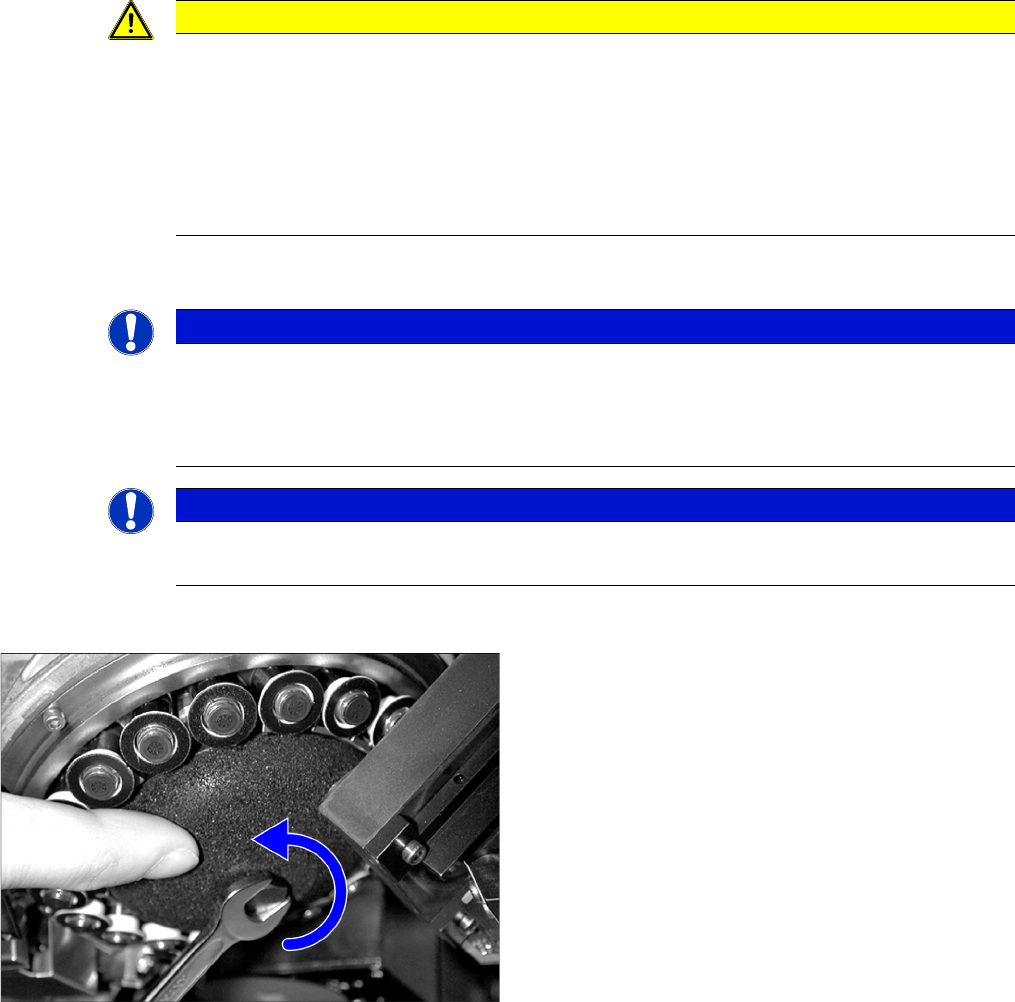
► Dismantle the silencer. To do this, loosen the screw
fastening the silencer and carefully lever the silencer
out.
► Check the silencer for contamination and replace, if
necessary.
Hand-tighten the screw fastening the silencer.
Maintenance
4.2.1 Checking/Replacing the Vacuum-Conducting Parts Maintenance Tasks for C&P20/A/M Head
Vacuum Pump Vakuumpumpe 117
Checking the Reflecting Rings (for Vacuum Pump Operation)
Checking the holding circuit (for compressed air operation)
► Fit the holding circuit and silencer again by following the above instructions in reverse order. This
task must be carried out by authorized personnel. For removal and installation details, read the ser-
vice manual for your machine. Also observe the following instructions:
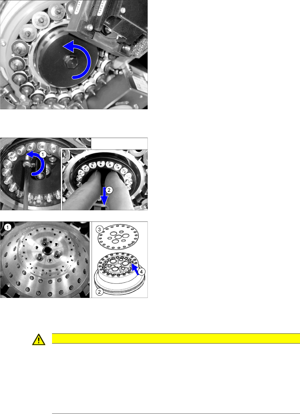
► Dismantle the reflecting ring. Loosen the screw fas-
tening the cover and remove the cover, together with
the reflecting ring.
► Check the sealing disk and the O-ring on the reflect-
ing ring for contamination and damage and replace
this if necessary.
Tighten the three fastening screws with a torque of
25+5 Ncm.
Hand-tighten the screw fastening the cover.
► Dismantle the vacuum distributor holding circuit.
► Only loosen the three protruding fastening screws on
the holding circuit and remove the holding circuit.
► Check the seat of the holding circuit (1) for dirt.
► Clean the seat with a lint-free cloth, if required.
► Check the holding circuit (2) and the seal (3) for dirt
and damage. If heavily soiled or damaged, replace
the holding circuit with a new one.
► Clean the holding circuit with compressed air. Make
sure that no dirt gets into the Venturi nozzles (4).
CAUTION
Installation instructions
► During fitting, make sure that the centering pin is inserted into the opposite hole in the seat
of the holding circuit, otherwise the holding circuit could be fitted at an incorrect angle (twist-
ed by 120 degrees).
► Make sure that the seal is inserted correctly!
► Tighten the three fastening screws of the holding circuit with 25+5 Ncm.
► Insert the silencer once more and screw it in place. The screw may only be tightened "hand-
tight".