00196845-02_AI_Vakuumpumpe_SXDX4_X-Serie-S_de_en - 第127页
Appendix 5.6.1 Replacing the Motor Circuit Breaker with Motor Pr otection Tripping Unit Excerpts from the Service Manual Vacuum Pump Vakuumpumpe 127 5.6.1.2 5 . 6 . 1 . 2 R e p la c in g t h e M o t o r P r o t e c t io …
Appendix
Excerpts from the Service Manual 5.6.1 Replacing the Motor Circuit Breaker with Motor Protection Tripping Unit
126 Vacuum Pump Vakuumpumpe
Overview
Removal
► Switch off the machine, disconnect it from the power supply and secure it to prevent unauthorized
reactivation. Observe the instructions in section "1.2 Preparatory Work..." [ ➙ 72].
► Unplug all connections to the motor circuit-breaker. You may want to mark their positions, to make
clear assignment easier later on.
Installation
► Follow the removal instructions in reverse order for installation.
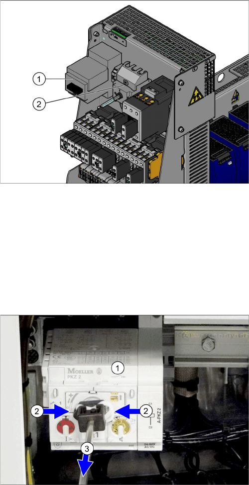
Motor circuit breaker and main switch (using example of
US version)
1. Motor circuit breaker
2. Main switch (US version only)
In non-US versions, the motor circuit breaker also serves
as the main switch.
► Remove the rod which connects the motor circuit
breaker (1) to the outer main switch handle. To do
this, press the white plastic clips together (2) and pull
off the rod (3).
► Take the motor circuit breaker off the rail.
Appendix
5.6.1 Replacing the Motor Circuit Breaker with Motor Protection Tripping Unit Excerpts from the Service Manual
Vacuum Pump Vakuumpumpe 127
5.6.1.2
5.6.1.2 Replacing the Motor Protection Tripping Unit (PKZ 2)
Replacing the Motor Protection Tripping Unit (PKZ 2)
Parts, Equipment and Tools
If you have supply voltages of 3x208 V~ and 3x230 V~, you will need to use the motor protection tripping
unit ZM-32-PKZ2 [00342496-xx].
▪ Motor protection tripping unit ZM-16-PKZ2 [00342495-xx] (default)
▪ Motor protection tripping unit ZM-32-PKZ2 [00342496-xx] (US version)
Overview
Removal
► Switch off the machine, disconnect it from the power supply and secure it to prevent unauthorized
reactivation. Observe the instructions in section "1.2 Preparatory Work..." [ ➙ 72].
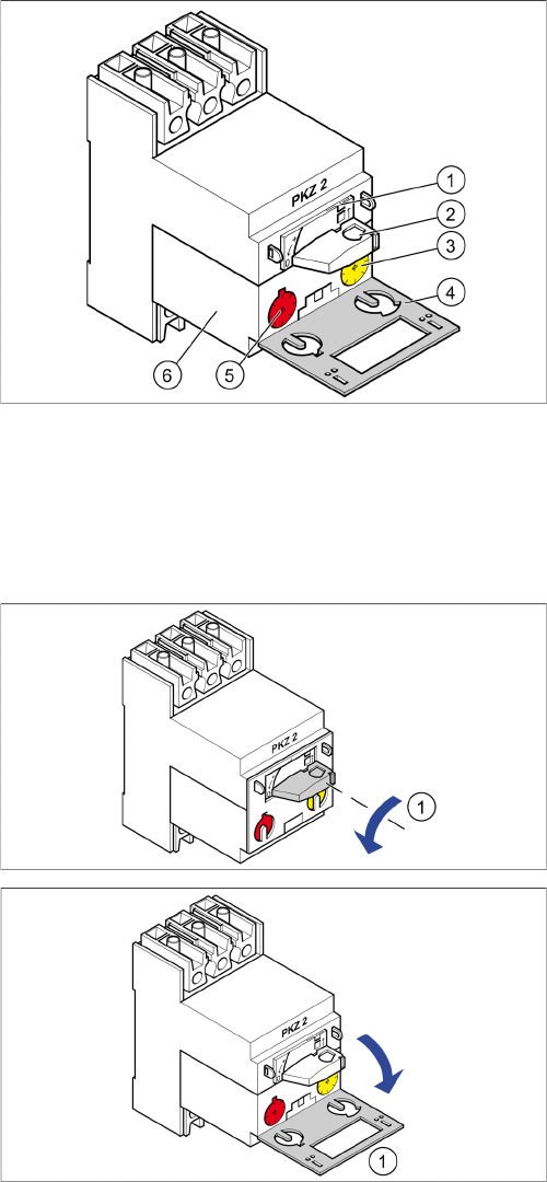
Motor circuit breaker
1. Locking tab
2. Rotary switch
3. Trigger threshold for overcurrent (yellow setting disk)
4. Protective flap
5. Trigger threshold for short-circuit current (red setting
disk)
6. Motor protection tripping unit
► Turn the switch (1) anticlockwise to the position "0"
► Open the protective flap (1).
Appendix
Excerpts from the Service Manual 5.6.1 Replacing the Motor Circuit Breaker with Motor Protection Tripping Unit
128 Vacuum Pump Vakuumpumpe
Installation
Motor protection tripping unit settings
► Check the trigger threshold for overcurrent (yellow setting disk)
► Check the trigger threshold for short-circuit current (red setting disk)
► Set the motor protection tripping unit
► Push the yellow locking tab downwards
► Close the gray protective flap.
► Turn the rotary switch clockwise as far as the stopper.
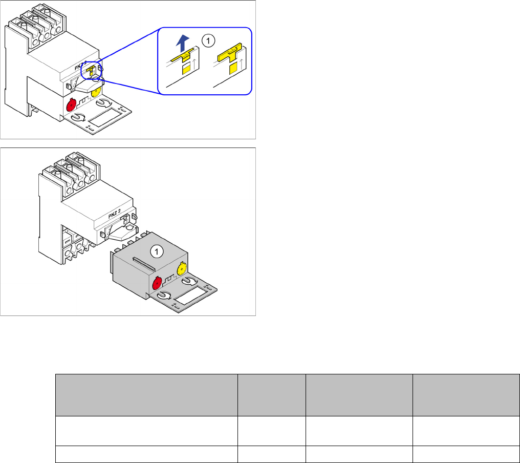
► Use a screwdriver to push the yellow locking tab (1)
upwards.
► Pull the motor protection tripping unit (1) out.
Motor protec-
tion tripping
unit
Yellow setting disk for
overcurent trigger
threshold
Red setting disk for
short-circuit current
trigger threshold
X series/SX4/DX4 for 3x110V~ +/-5%
(US version)
ZM-32-PKZ2 24 A 375 A
X series/SX4/DX4 for 3x230V~ +/-5% ZM-16-PKZ2 16 A 200 A