00196845-02_AI_Vakuumpumpe_SXDX4_X-Serie-S_de_en - 第130页
Appendix Excerpts from the Service Manual 5.6.1 Replacing the Motor Circu it Breaker with Motor Protection Tripping Unit 130 Vacuum Pump Vakuumpumpe Removal ► Switch off the machine, disconnec t it from the po wer supply…
Appendix
5.6.1 Replacing the Motor Circuit Breaker with Motor Protection Tripping Unit Excerpts from the Service Manual
Vacuum Pump Vakuumpumpe 129
5.6.1.3
5.6.1.3 Replacing the Motor Circuit Breaker PKE32/XTU-32 [03098183-xx]
Replacing the Motor Circuit Breaker PKE32/XTU-32 [03098183-xx]
Missing Axis Support – TI2013-07D10
Parts, equipment and tools
▪ Motor circuit breaker PKE32/XTU-32 assembly 3p. [03098183-xx]
The motor circuit breaker is supplied together with the tripping unit.
▪ Technical information "Retrofit Guide Axis Support Motor Circuit Breaker PKE32/XTU-32 Assembly
3p. (Main Switch)" [DE: TI2013-07D10] [EN: TI2013-07E10].
Overview
CAUTION
New version
Do not confuse this version of the motor circuit breaker with the old one. Pay particular attention
to the settings.
NOTICE
Missing axis support
The machine is switched on with the help of an extension axis via the motor circuit breaker.
When inserting the door coupling handle onto the extension axis of the motor circuit breaker,
the axis could move into a slanted position. In this case, high traverse forces will be exerted
against the axis coupling of the motor circuit breaker, which could then break. This would then
make it impossible to switch the machine on or off.
Some machines do not have this additional axis support on the motor circuit breaker. This sup-
port is used to limit the slant of the extension axis and therefore to reduce the traverse forces
against the axis coupling.
► This axis support can be retrofitted. For details, read the technical information "Retrofit
Guide Axis Support Motor Circuit Breaker PKE32/XTU-32 Assembly 3p. (Main Switch)"
[DE: TI2013-07D10] [EN: TI2013-07E10].
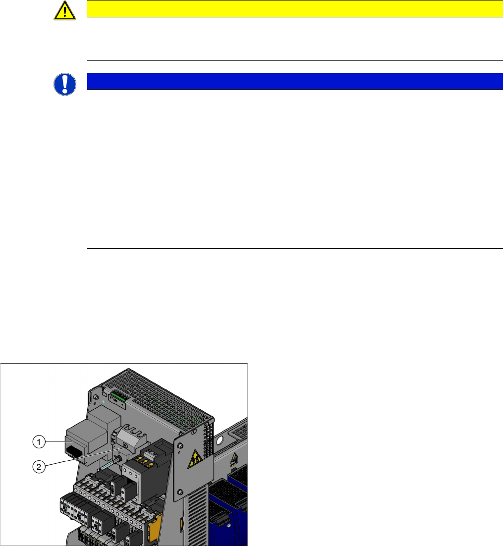
Motor circuit breaker and main switch (using example of
US version)
1. Motor circuit breaker
2. Main switch (US version only)
In non-US versions, the motor circuit breaker also serves
as the main switch.
Appendix
Excerpts from the Service Manual 5.6.1 Replacing the Motor Circuit Breaker with Motor Protection Tripping Unit
130 Vacuum Pump Vakuumpumpe
Removal
► Switch off the machine, disconnect it from the power supply and secure it to prevent unauthorized
reactivation. Observe the instructions in section "1.2 Preparatory Work..." [ ➙ 72].
► Unplug all connections to the motor circuit-breaker. You may want to mark their positions, to make
clear assignment easier later on.
Installation
► Follow the removal instructions in reverse order for installation. Also observe the following instruc-
tions:
Settings
► Set the trigger threshold for the nominal current (left setting disk).
► Set the trigger threshold for the overload class (right setting disk).
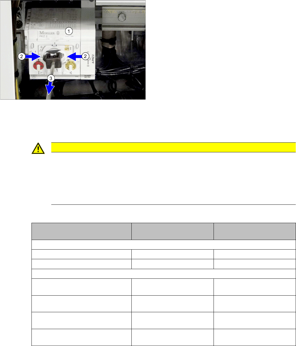
► Remove the shaft which connects the motor circuit
breaker (1) to the outer main switch handle. To do
this, press the white plastic clips together (2) and pull
off the shaft(3).
► Loosen the latch for the motor circuit breaker on the
rail and remove the motor circuit breaker. You may
need to read the manufacturer's instructions provid-
ed.
CAUTION
Installation instructions
► Please observe the instructions for correct assembly in the technical information "Retrofit
Guide Axis Support Motor Circuit Breaker PKE32/XTU-32 Assembly 3p. (Main Switch)"
[DE: TI2013-07D10] [EN: TI2013-07E10].
► Remove the shaft from the old switch and fit it on the new switch.
► Set the nominal current and overcurrent (see below)
Motor protection tripping unit
PKE-ZTU-32
Left setting disk
for nominal current
Right setting disk
for overcurrent class
SX1/SX2
3x380V - 3x 415V 8 A 5
3x200V - 3x 230V 13.5 A 5
X series S, SX4/DX4
3x380V to 3x415V
One vacuum pump or none
8 A 5
3x200V - 3x230V
One vacuum pump or none
13.5 A 5
3x380V to 3x415V
Two vacuum pumps
13.5 A 5
3x200V to 3x230V
Two vacuum pumps
17.2 A 5
acpage