00196845-02_AI_Vakuumpumpe_SXDX4_X-Serie-S_de_en - 第96页
Fitting the Vacuum Pump Changeover 3.2.6 Installation Locations for Vacuum Pumps 96 Vacuum Pump Vakuumpumpe 3.2.5.4 3 . 2 . 5 . 4 P r e p a r in g t h e D is t r ib u t o r B lo c k Preparing the Distributor Block 3.2.6 …

Fitting the Vacuum Pump
3.2.5 Prefitting the Vacuum Pump Changeover
Vacuum Pump Vakuumpumpe 95
► Apply Loctite 55 to the threaded connection and
screw in the "fitting G1-G3/4" [03088251-xx (1) in
place of the leakage valve.
► Place the cover back and fix it with the two screws
which you removed.
► Screw the "double nipple, detachable G3/4 Ms"
[03038435-xx] apart and screw one half (1) into the
fitting. Apply Loctite 55 to the threaded connection.
Observe the installation instructions from the pump
manufacturer. The thread sealing cord must be
wound on in the direction of the thread.
► Screw the second half (2) of the "detachable double
nipple"[03038435-xx] into the filter (3). Apply Loctite
55 to the threaded connection.
Observe the installation instructions from the pump
manufacturer. The thread sealing cord must be
wound on in the direction of the thread.
1. Filter [03070370-xx]
2. Eleven o'clock position
► Screw the filter [03070370-xx] onto the first half of the
double nipple and into the pump. First apply Loctite
55 to the threaded connection.
► Correctly position the filter. The connecting piece
must point to 11 o'clock (1).
► Use the "spanner wrench SW36" [03090043-xx] to
tighten the nut.
► (1) Screw a double nipple G3/4 brass [03093668-xx]
into the filter. First apply Loctite 55 to the threaded
seal.
Fitting the Vacuum Pump
Changeover 3.2.6 Installation Locations for Vacuum Pumps
96 Vacuum Pump Vakuumpumpe
3.2.5.4
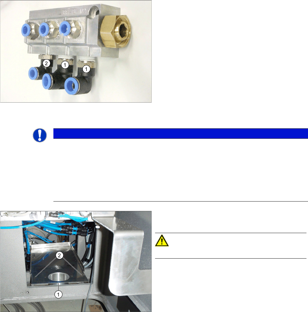
3.2.5.4 Preparing the Distributor Block
Preparing the Distributor Block
3.2.6
3.2.6 Installation Locations for Vacuum Pumps
Installation Locations for Vacuum Pumps
Prepare the distributor block. The distributor block is con-
nected to the filter connection piece after installation of
the pump in the machine.
1. Size 12 angular coupling (2x)
Push-in fitting QSL-1/2-12 [03080578-xx] (L-angle
screwed fitting)
2. Size 10 angular coupling (1x)
Push-in fitting QSL-1/2-10 [03081051-xx]
► Rotate the size 10 or size 12 angular couplings into
the distributor block, as shown in the diagram.
NOTICE
Installation locations
The vacuum pumps are fitted in placement area 1, at locations 1 and 4.
If only one vacuum pump is fitted, this is installed at location 4.
► In SX4/DX4 machines, the vacuum pump at location 4 supplies placement area 2 and the
vacuum pump at location 1 supplies placement area 1.
► In X series S machines, the vacuum pump at location 4 supplies placement area 1 and the
vacuum pump at location 1 supplies placement area 2.
Support sheet in the machine (delivery state)
1. Exhaust pipe
2. Screws fastening the support sheet
CAUTION!
Make sure you do not bend or damage any cables.
Fitting the Vacuum Pump
3.2.7 Connecting and Running Hoses Changeover
Vacuum Pump Vakuumpumpe 97
3.2.7
3.2.7 Connecting and Running Hoses
Connecting and Running Hoses
The following hose-related tasks are performed either at location 1 or 4, depending on the point of instal-
lation (see "3.2.6 Installation Locations for Vacuum Pumps" [ ➙ 96]).
► Perform the above mentioned tasks for all gantries to be converted.
► Fasten the vacuum hoses for the unconverted gantries with a cable tie and push these hoses up-
wards in the machine base, to make room for installation of the pump.
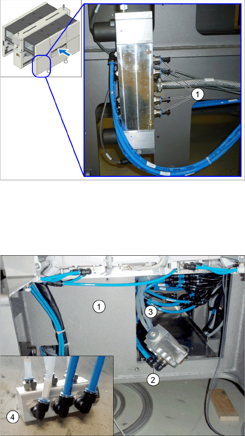
Proportional valve (already without hoses here, with
blanking plugs)
We always recommend connecting the hoses for a spe-
cific placement area one after another to the vacuum
pump. If you are converting multiple gantries, disconnect/
reconnect the hoses for one gantry at a time, to prevent
unintentional confusion of gantry hose assignment.
► Localize the hose for the gantry to be converted at the
proportional valve distributor (location 4) and discon-
nect this hose.
► Close the opening with a blanking plug (1).
► Pull the hose disconnected from the proportional
valve back to the vacuum pump installation point and
connect it to the vacuum distributor (4).
► Pull the transparent vacuum hoses (two per gantry)
belonging to the gantry to be converted out of the ma-
chine base.
The vacuum hoses are present in their maximum
length in the machine.
► Shorten the two vacuum hoses to the length required
to connect them to the vacuum distributor, which will
be run inside the machine base at (1).
► Mark the vacuum hoses with the relevant gantry num-
ber.
► Connect the size 12 PUN hose (2) and the vacuum
hoses (3) to the vacuum distributor.