00196845-02_AI_Vakuumpumpe_SXDX4_X-Serie-S_de_en - 第98页
Fitting the Vacuum Pump Changeover 3.2.8 Rewiring the I/O Distributor 98 Vacuum Pump Vakuumpumpe 3.2.8 3 . 2 . 8 R e w ir in g t h e I / O D is t r ib u t o r Rewiring the I/O Distributor 3.2.9 3 . 2 . 9 R u n n in g t h…
Fitting the Vacuum Pump
3.2.7 Connecting and Running Hoses Changeover
Vacuum Pump Vakuumpumpe 97
3.2.7
3.2.7 Connecting and Running Hoses
Connecting and Running Hoses
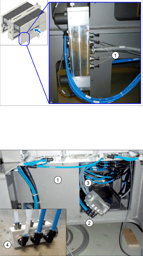
The following hose-related tasks are performed either at location 1 or 4, depending on the point of instal-
lation (see "3.2.6 Installation Locations for Vacuum Pumps" [ ➙ 96]).
► Perform the above mentioned tasks for all gantries to be converted.
► Fasten the vacuum hoses for the unconverted gantries with a cable tie and push these hoses up-
wards in the machine base, to make room for installation of the pump.
Proportional valve (already without hoses here, with
blanking plugs)
We always recommend connecting the hoses for a spe-
cific placement area one after another to the vacuum
pump. If you are converting multiple gantries, disconnect/
reconnect the hoses for one gantry at a time, to prevent
unintentional confusion of gantry hose assignment.
► Localize the hose for the gantry to be converted at the
proportional valve distributor (location 4) and discon-
nect this hose.
► Close the opening with a blanking plug (1).
► Pull the hose disconnected from the proportional
valve back to the vacuum pump installation point and
connect it to the vacuum distributor (4).
► Pull the transparent vacuum hoses (two per gantry)
belonging to the gantry to be converted out of the ma-
chine base.
The vacuum hoses are present in their maximum
length in the machine.
► Shorten the two vacuum hoses to the length required
to connect them to the vacuum distributor, which will
be run inside the machine base at (1).
► Mark the vacuum hoses with the relevant gantry num-
ber.
► Connect the size 12 PUN hose (2) and the vacuum
hoses (3) to the vacuum distributor.
Fitting the Vacuum Pump
Changeover 3.2.8 Rewiring the I/O Distributor
98 Vacuum Pump Vakuumpumpe
3.2.8
3.2.8 Rewiring the I/O Distributor
Rewiring the I/O Distributor
3.2.9
3.2.9 Running the Supply Cable
Running the Supply Cable
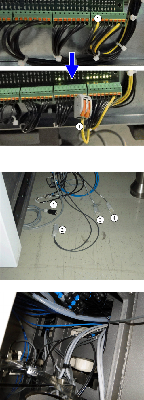
► Remove the center cover from the control computer
side.
► Disconnect the cable x3qb (1) from the distributor
and secure it with a Wago terminal to prevent a short-
circuit.
► Refit the center cover and fix it into place.
Location 2
1. Pump cable (one or two, depending on how many
pumps are fitted)
2. Fan cable
3. Power supply [03076872-xx] (in the machine)
4. Control system [03076480-xx] (in the machine)
► Run the cable for the voltage supply and control from
location 1 and, if necessary, from location 4 to loca-
tion 2 (PA2).
Location 1
► Place the cable over the sheet in PA2.
Fitting the Vacuum Pump
3.2.9 Running the Supply Cable Changeover
Vacuum Pump Vakuumpumpe 99
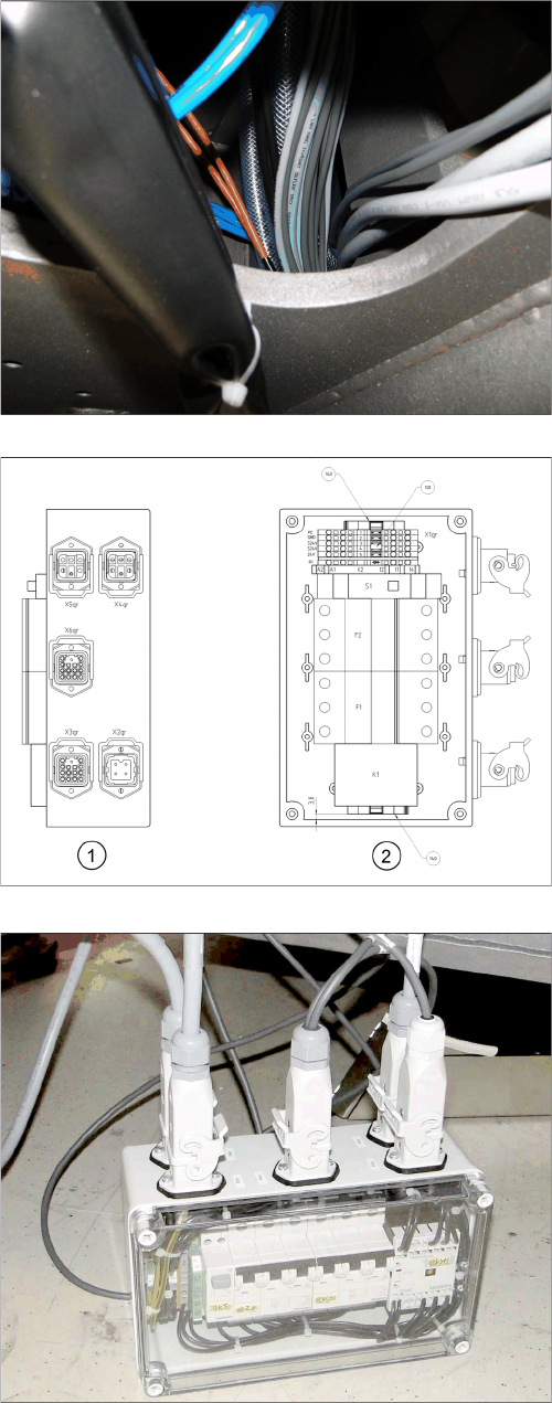
Location 2
Connection unit assembly
1. Side view: connection side
2. View from above
► Connect the cable to the vacuum pump connection
unit:
X2pr: voltage
X3pr: control
X4pr: pump 1
X5pr: pump 2
X6pr: fan
► If you connect only one pump, close the second con-
nection with a bridge connector [03055299-xx]. This
is provided with the "Vacuum pump connection unit
assembly [03079448-xx].
► After the function test, stow the connection unit in the
machine base.