PI series 3D SPI-brochure - 第6页
10 11 INSPECTION TECHNOL OGY PI PICO PI PRIMO 3D e ng in e 36 0 ° Moir é - Sh a dow fre e, Mu lti- c a me ra , Mul ti- pro je c tor, Mu lti -p at ter n Camera 8 0 Mp ixel , 12- bit C M OS s en so r 1 60 M pi xel , 12- bi…
8 9
Measure paste volume
with unmatched accuracy
Take control
over your print process
The PI Series’ patented Z-referencing technology captures
hundreds of references across an ultra-large 3D field of view,
giving you unprecedented accuracy for even the smallest paste
volume measurements.
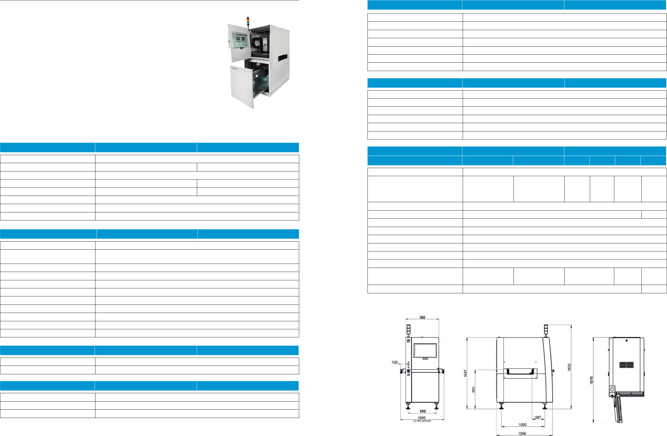
PI’s automatic pad grouping by AAR (Area Aperture Ratio) allows you
to continuously improve your process and set tolerances independently
of products. Together with the SIGMA Link software suite, this means you
can transform your inspection data into actionable process information.
• Highly accurate paste volume
measurement using a patented
Z-referencing technology that
overcomes the limitations of
traditional SPI systems.
• Superior accuracy in real
production environments,
with no false calls due to a
unique warp compensation
enabled by multi-frequency,
multi-pattern moiré,
combined with patented
dual Z-axis motion.
• Unambiguous information
for defect classification with
high-resolution textured 3D
images.
• Improve your process and set
tolerances independently of
products with meaningful auto-
matic pad grouping by AAR.
• Gain new insights into your
process with extra-large review
images in textured 3D for easy
diagnostics.
• Monitor your process in real
time with SIGMA Analysis,
which helps you report and
monitor your progress with
useful trend analyses.
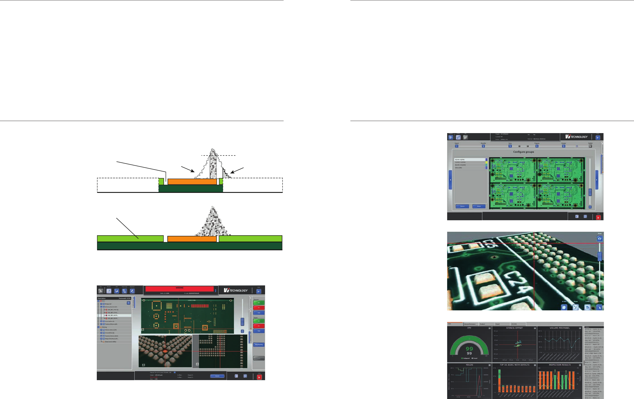
Traditional SPI: The typical threshold for a traditional SPI is usually 40
micrometers (μm), meaning height and volume under this limit goes
unmeasured. As a result, volume is underestimated on small pads, precisely
when you need to know how much paste is truly deposited.
PI Series: PI’s patented Z-referencing method leverages the entire textured
3D board information, rather than just cropped images around the pads, to
define a stable and accurate Z-reference.
Traditional SPI
PI
Unstable Z-reference
Stable Z-reference
Not measured
Not measured
Threshold @ 40 μm
10 11
INSPECTION TECHNOLOGY PI PICO PI PRIMO
3D engine 360° Moiré - Shadow free, Multi-camera, Multi-projector, Multi-pattern
Camera 80 Mpixel, 12-bit CMOS sensor 160 Mpixel, 12-bit CMOS sensor
Image resolution 15 μm
Projection 4 HD, 10-bit industrial projectors 8 HD, 10-bit industrial projectors
Field of View (X x Y) 160 mm x 55 mm 350 mm x 55 mm
Lighting White LED + RGB lighting
Warp compensation +/- 5 mm with dual Z axis motion for real time Z and θ adjustments
Z-reference Full PCB inspection for Z-referencing with no cropping around pads
INSPECTION PERFORMANCE PI PICO PI PRIMO
Measurements Height, Area, Volume, O set, Bridging, Shape 2D, Shape 3D, Coplanarity
Defect types Insu cient / Excessive / Missing paste, Bridge, Shape 2D, Shape 3D,
User defi ned defect, Foreign material, Paste pollution
Minimum paste deposit size 150 μm x 150 μm
Maximum paste deposit size 20 mm x 20 mm
Maximum paste height 400 μm (consult for higher paste height)
Height resolution 100 nm
Height acurracy < 2 μm on Certifi cation target at operating temperature
Height repeatability < 1 μm @ 3σ on Certifi cation target at operating temperature
Volume repeatability < 3% @ 3σ on PCB at operating temperature
Gage R&R < 10%
Inspection speed 3 sec per Field of View
SOFTWARE SUITE PI PICO PI PRIMO
O ine programming software SIGMA Data Import (Gerber, CAD data, glue deposit data)
Online SPC Alerts in case of process drift
SYSTEM PI PICO PI PRIMO
Operating system Linux
Storage capacity 6TB including 4TB in RAID 1
Axis motion Stepper motor and linear optical encoder (1μm resolution)
OPTIONS PI PICO PI PRIMO
External barcode readers (1D/2D) Cognex DM 150 (requires 1000mm conveyor)
Internal barcode readers (1D/2D) Software option enabling reading from inspection head
Uninterruptible power supply For PC / 230 V
Closed loop with stencil printer Available for all major stencil printer brands
Glue deposit inspection Simultaneous inspection for paste and glue
M2M conveying mode Kit to implement IPC HERMES 9852 protocol
Other options available Please contact us
FACILITIES PI PICO PI PRIMO
Interface IPC-SMEMA-9851
Power requirements Single Phase 2P+ Earth, 100 - 240 VAC / 16A, no need for compressed air
Dimensions in mm (W x D x H) 1000 (800 optional) x 1296 x 1932 (adjustable height)
Weight 430 kg
Operating temperature 15°C to 30°C
Relative humidity 20-75% (without condensing)
PCB HANDLING PI PICO PI PRIMO
S M S M L XL
Minimum PCB dimensions 51 mm x 51 mm (2 x 2 inch)
Maximum PCB dimensions (X x Y) 350 x 533 mm
(14 x 21 inch)
533 x 533 mm
(21 x 21 inch)
350 x
533 mm
(14 x 21
inch)
533 x
533 mm
(21 x 21
inch)
609 x
533 mm
(24 x 21
inch)
762 x
533 mm
(30 x 21
inch)
Minimum PCB thickness 0,1 mm
Maximum PCB thickness 5 mm 7,5 mm
Minimum edge clearance 3 mm
Top clearance 20 mm
Bottom clearance 50 mm
Conveying direction Left to right - Right to left - Left to left - Right to right
Conveyor width adjustment Automatic
Conveying height 830 mm to 930 mm (standard) / 900 mm to 1000 mm (option)
Conveyor lenght 1000 mm (standard)
800 mm (option)
1000 mm 1000 mm (standard)
800 mm (option)
1000 mm 1250 mm
Maximum PCB weight 4 kg 4,5 kg
DIMENSIONS PI PICO AND PI PRIMO
Robust conception, smart access and built-in manual
for fast and easy maintenance, every aspect has been
designed to simplify your operations.
PI series 3D SPI
State
-
of
-
the
-
art design

4030822 Rev 0001 / March 2020
NETHERLANDS
Mycronic B.V.
High Tech Campus 10
5656 AE
Eindhoven
Netherlands
Tel: +31 402 62 06 67
SINGAPORE
Mycronic Pte., Ltd.
9 Tagore Lane, #02-08/09
9@Tagore
Singapore 787472
Tel: +65 6281 7997
SOUTH KOREA
Mycronic Co. Ltd.
3rd Floor, Jung-San
Bldg. 1026-8
Sanbon-Dong, Gunpo-Si
Gyeonggi-Do, 15808
South Korea
Tel: +82 31 387 5111
UK
Mycronic Ltd.
Unit 2, Concept Park
Innovation Close
Poole, Dorset, BH12 4QT
UK
Tel: +44 1202 723 585
USA
Mycronic Inc.
320 Newburyport Turnpike
Rowley, MA 01969
USA
Tel: +1 978 948 6919
mycronic.com
SWEDEN
Mycronic AB
PO Box 3141
Nytorpsvägen 9
SE-183 03 Täby
Sweden
Tel: +46 8 638 52 00
CHINA
Mycronic Co., Ltd
Unit 106, E Block
Lane 168, Da Duhe Road.
Putuo District, 200062
Shanghai P.R. China
Tel: +86 21 3252 3785/86
FRANCE
Mycronic S.A.S.
1 rue de Traversière - CS 80045
94513 Rungis Cedex 1
France
Tel: +33 1 41 80 15 80
Vi TECHNOLOGY
Rue de Rochepleine
38120 Saint Egrève
France
Tel: +33 4 7675 8565
GERMANY
Mycronic GmbH
Biberger Straße 93
D-82008 Unterhaching bei München
Germany
Tel: +49 89 4524248-0
JAPAN
Mycronic Technologies KK
Chofu Center Bldg.
1-18-1 Chofugaoka, Chofu-shi
Tokyo 182-0021
Japan
Tel: +81 42 433 9400
Specifications are subject to change without notice.
Mycronic, MYDATA, MYDATA automation and MY; Mycronic 4.0; MYPro, MY100, MY100e, MY200, MY200HX, MY200DX, MY200SX, MY200LX, MY300, MY300DX, MY300SX,
MY300LX, MY500, MY600, MY600JD, MY600JP, MY600JX, MY700, MY700JD, MY700JP, MY700JX and MYSynergy; Mycronic 4.0; MYSmart, MYC50, MYD10, MYD50, MYT10, MYT50;
Mycronic SMD Tower; Vi TECHNOLOGY, VIT; 5K, 5K3D, 8K, 8K3D, 9K, 9K3D; PI, PI Pico, PI Primo; SIGMA Link; HYDRA Speedmount, Midas, ISIC; Agilis, Agilis Linear Magazine (ALM),
Agilis Linear Magazine Flex (ALM FLEX), Agilis Stick Magazine (ASM), Agilis Tray Magazine (ATM), Mycronic Tray Exchanger (TEX), Mycronic Tray Wagon Magazine (TWM); Mycronic
Dip Unit (DPU); Mycronic Standard Vision System (SVS), Mycronic Dual Vision System (DVS), Mycronic Linescan Vision System (LVS), Mycronic HYDRA Vision System (HVS); Mycronic
Assembly Process Management (APM) including; JPSys, TPSys, MYLabel, MYPlan, MYCenter, MYTrace, MYCam and FlowLine are registered trademarks or trademarks of Mycronic AB.
Mycronic AB is ISO 9001:2015 and ISO 14001:2015 certified.