00191376-07.pdf - 第44页
7 4-monthly maintenance jobs HS Preventive Maintenance 01/2006 US E dition 44 7

HS Preventive Maintenance 7 4-monthly maintenance jobs
01/2006 US Edition
43
7
You will need the following tools, equipment and consumables for the 4-monthly maintenance. 7
–Pliers
– Short-bristled brush
– Set of hexagon socket spanners
– Lint-free cloths
– Lint-free cottonwool buds
– Ethyl alcohol
– ISOFLEX TOPAS NCA52 grease
– UNISILKON L250L
– Oil dispenser with Structovis GHD (DLM1)
– New distributor plate, if required (DLM 1)
– New Z axis toothed belt, if required
– New distributor, if required
– New O-ring, turning station, if required
– New toothed belt for the turning station, if required.
– Set of cleaned sleeves
– Set of clean valve plungers
7
7
7
7
7
7
7 4-monthly maintenance jobs HS Preventive Maintenance
01/2006 US Edition
44
7

HS Preventive Maintenance 7 4-monthly maintenance jobs
01/2006 US Edition
45
Dismantle front part of head 7
: Use the "Single Functions" menu to return the nozzles of every Collect&Place head to the noz-
zle changer.
: Shut down the operating system and switch off the placement machine at the main switch.
7
: Loosen the screws on the head cover.
: Remove the head cover.
Remember to follow the ESD regulations.
7
7
: Cover the feeder area to protect the feeder modules and front part of the head.
7
: Unplug the ribbon cables for the front part of head on the conversion board carefully.
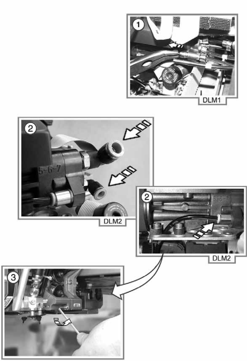
a Detach the compressed air hose.
Use suitable pliers to do this. 7
7
7
7
7
We recommend that you label or otherwise mark the compressed air hoses before you remove
them. 7
On the DLM1 heads, the hoses are already labeled and have a fixed assignment. 7
7
: Turn the star half a revolution to avoid damaging the valve plunger drive with the valve plungers
when removing the front part.
s Loosen the 3 screws (DLM1) or 4 screws (DLM2) on the front part of head (using the 3 mm
socket-head spanner) and remove the front part.
Hold the front part of head firmly as you remove the screws. 7
Watch out for the distributor plate and the distributor. 7
7
7
: Place the front part of head on a soft ESD surface (with the valve plunger side underneath) or
place it on a suitable head stand.
: Remove the sleeves and place them in the containers provided.