Portal_Manual_1.2.1_Rev_H-1.pdf - 第41页
Portal PVA Revisio n H ( 2018 ) 41 of 93 8. Weigh the dispensed quantity of material in grams. Subtr act the weig ht of the cup if necessary. 9. Find the volume i n cc with the equat ion below : Grams of material/specifi…

Portal
PVA
Revision H (2018)
40 of 93
8.3.4 Auto Cycle Flow Error
Auto Cycle checks the material flow after every cycle if the error is turned “ON” in the
Flow Control mode. If the volume is within parameters, no indication is shown. When
the volume is outside the parameters, the flow error screen is shown when the cycle
completes (not immediately on error).
Remove the part before operating the workcell again.
NOTE: Any changes made to settings in the material delivery system (material
pressure, stroke adjustment, etc.) will affect the data from the flow monitor.
When this happens, it will be necessary to find the correct material volume
again.
8.3.5 Flow Monitor Calibration
The flow monitor on the workcell measures the amount of material that moves through
the material supply line before it splits to supply individual valves. It does not control
the process, but reports deviations from the set values. Both the necessary material
volume and the permitted deviation are determined by the operator. The flow monitor
calibration should be examined once a month or if any changes are made to the fluid
delivery system.
This procedure is to calibrate a single flow monitor, if the specific gravity of the
dispensed material is known. This procedure would calibrate the A flow monitor, to
calibrate the B, C, and D monitors replace the variable DEZ, with DEW, DEE, and DEF
respectively, as well as FCA_CAL, with FCB_CAL, FCC_CAL, and FCD_CAL. See the Chart
at the bottom of the page for the variables relating to each monitor.
1. Login to Portal.
2. Make sure the workcell is in Manual Mode.
3. Select the Terminal tab on the right side of the Portal screen to open the
terminal screen.
4. Type DEZ=0 (for first flow monitor only) in the top section of the terminal screen
and select the “Enter” button on the keyboard. This resets the flow monitor
encoder to zero.
5. Weigh an empty purge cup and record the weight, or zero the scale with the
empty purge cup on it.
6. Purge a quantity of material into the purge cup.
7. Type DEZ=? into the terminal and select the “Enter” button on the key board. A
number will return (ex. 50 counts per cc dispensed). The factory set value is
1000cnt/cc. If zeros are returned or incorrect data, type MG_DEZ=?

Portal
PVA
Revision H (2018)
41 of 93
8. Weigh the dispensed quantity of material in grams. Subtract the weight of the
cup if necessary.
9. Find the volume in cc with the equation below:
Grams of material/specific gravity=cc
Ex: .500g/.96=.5208cc
10. Use this value (in cc) to find the correct number of counts per cc dispensed.
Counts/cc= counts per cc
Ex: 25counts/.5208cc= 48.003 counts per cc
11. Do this procedure at least three times and average the results.
12. Open the Main Program in a text editor such as Windows NotePad.
13. Search for the variable: FCA_CAL= It will be in the section titled: REM !!!!
Machine-Specific Information!!!!
14. Type in the new value for FCA_CAL= (Ex: FCA_CAL=48.003)
15. Download the modified main program and test changes.
Flow Monitor
Variables
A
DEZ FCA_CAL
B
DEW FCB_CAL
C
DEE FCC_CAL
D
DEF FCD_CAL
Table 1: Flow Monitor Variables
Portal
PVA
Revision H (2018)
42 of 93
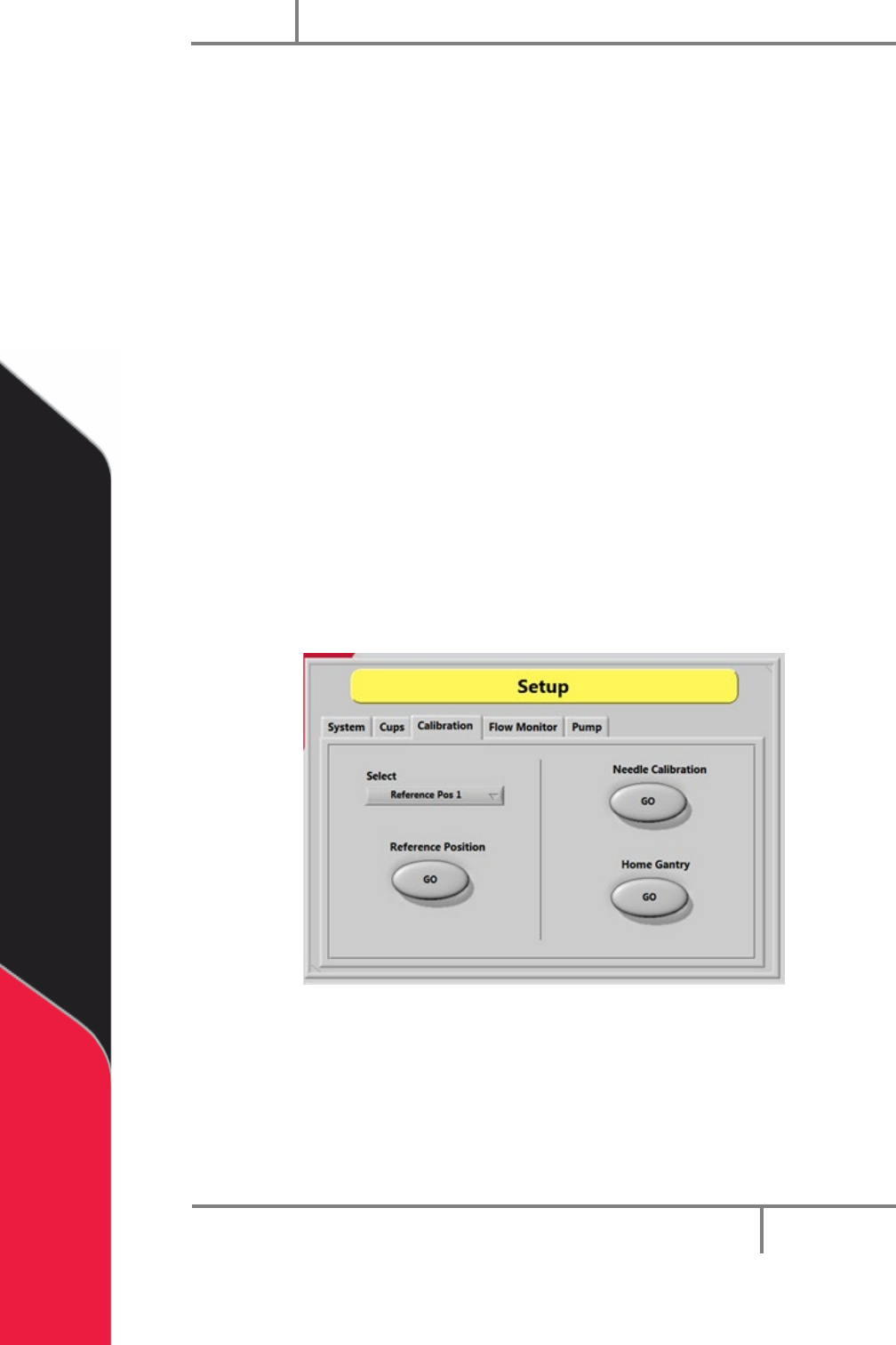
8.4 Needle Calibration
The workcell has one of three calibration methods: Standard, Operator Defined, and
Sensor Defined. If a sensor defined or operator defined method is installed on the
workcell, the machine may or may not automatically enter its particular calibration
mode when you enter Auto mode. This will depend on the application the workcell was
set up for. Refer to Sections 8.4.1-8.4.3 for information on different calibration
sequences.
8.4.1 Standard Needle Calibration
Standard needle calibration is the easiest calibration procedure.
1. Select the “Calibration” tab in Setup mode.
2. Select the necessary valve or tool from the drop down “Select” menu.
3. Select the Reference Position “GO” button. The selected valve will move to the
calibration point.
4. Examine the position of the needle as it relates to the calibration point (such as
cross-hairs).
5. If the needle is not directly above the point, use your hands to bend the needle
or adjust the tool position so the needle is above the calibration point.
Figure 28: Needle Calibration