Portal_Manual_1.2.1_Rev_H-1.pdf - 第37页
Portal PVA Revisio n H ( 2018 ) 37 of 93 8.2 Auto Purg e /Solv ent Cups Se tup Fig ure 27 : Auto Purg e and Solvent Cups Setup With the cup s tab you ca n set t he purge and/or so lvent cup feat ures . Auto purge dispens…
Portal
PVA
Revision H (2018)
36 of 93
8 Setup Mode
The options shown in Portal depend on the workcell configuration. Refer to your
machine specific manuals and appendices for more information.
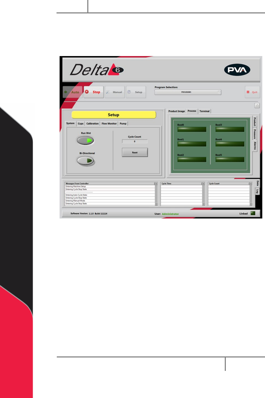
Figure 26: Setup Mode
In Setup mode you can control basic workcell functions. Auto Cycle parameters and
some workcell parameters are set in Setup Mode.
8.1 System
1. Select the “System” tab.
2. Select “Run Wet” to toggle it on or off. Valve operation is off for Auto Cycle
when the Run Wet is set to off. This does NOT affect the run option in the
Manual mode. There is a separate option in Manual mode to select “Wet” or
“Dry”.
3. Select “Bi-Directional” to toggle between single and bi-directional in auto cycle
(on machines that have that option).
4. Select “RESET” to reset the cycle count to zero.
5. Select “Stop” to leave Setup mode and go to Cycle Stop.
Portal
PVA
Revision H (2018)
37 of 93
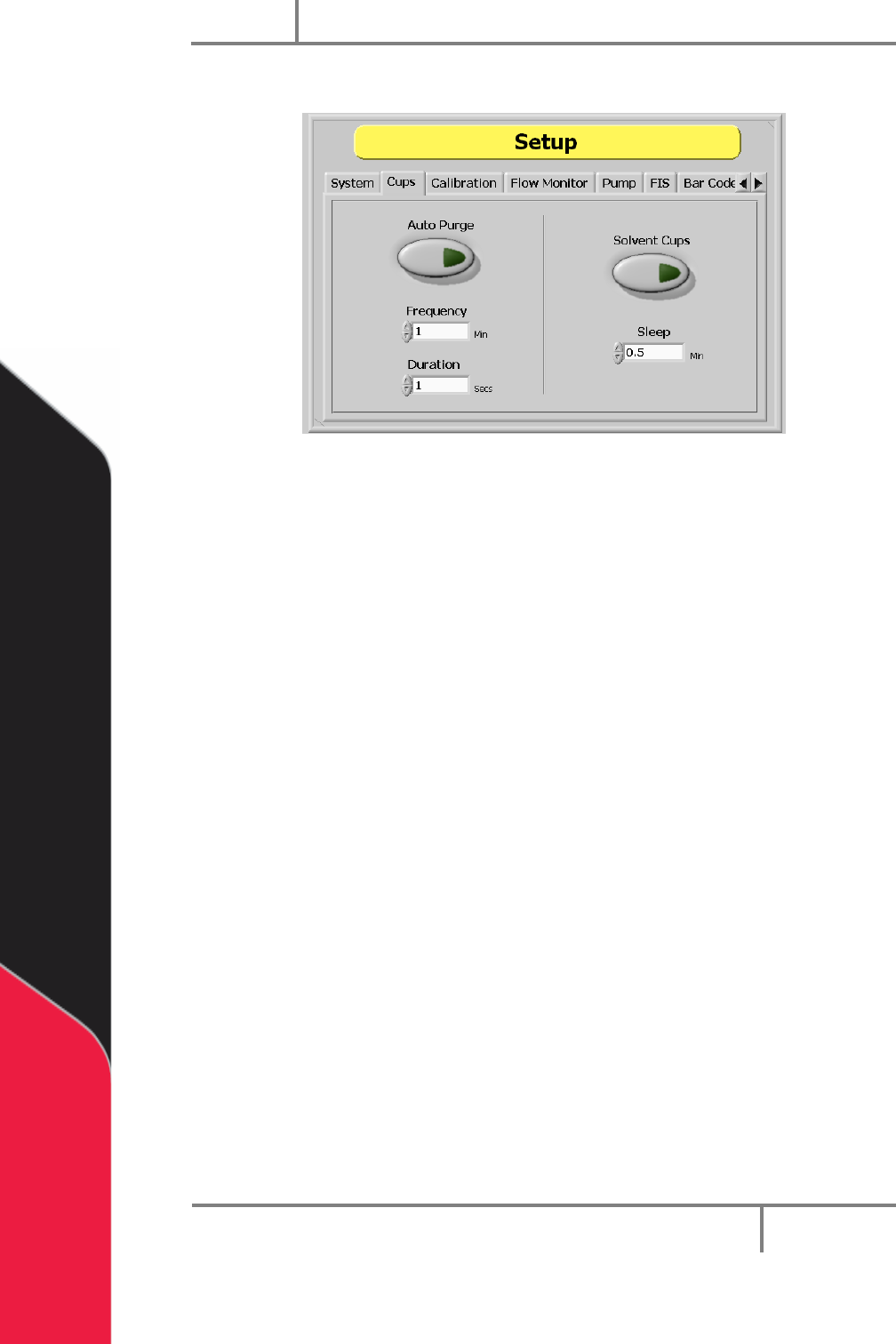
8.2 Auto Purge/Solvent Cups Setup
Figure 27: Auto Purge and Solvent Cups Setup
With the cups tab you can set the purge and/or solvent cup features. Auto purge
dispenses material from all valves at specific intervals to stop valves from clogging. The
default setting depends on the material used. The workcell only auto purges when in
Auto Cycle or Cycle Stop. The workcell does not auto purge in other modes but will
immediately auto purge when returned to Cycle Stop or Auto Cycle, if necessary.
NOTE: If the workcell has solvent cups, the solvent cup routine overrides the
auto purge settings. The system will only purge when necessary with the solvent
cup sequence.
1. Select the “Cups” tab.
2. Select “Auto Purge” to set the function to on or off. Solvent cups must be off for
the auto purge function to work.
3. Use the up and down arrows to set the Frequency in minutes of how often the
valves will purge. Or, type the necessary value in the box.
4. Use the up and down arrows to set the Duration in seconds for the time the
valves will purge for (applies to both auto purge and solvent options). Or, type
the necessary value in the box.
5. Select “Solvent Cups” to turn the solvent cups on or off. When the solvent cups
are on, the auto purge function is overridden. The valves will purge any time
they move out of the solvent position (not in manual mode).
6. Use the up and down arrows to set the “Sleep” value in minutes. Or, type the
necessary value in the box. The sleep value is duration of inactivity during auto
cycle before the heads move to the solvent cups.

Portal
PVA
Revision H (2018)
38 of 93
8.3 Flow Monitor (Optional)
The Flow monitor will always be in setup tree with only on/off settings. Setpoint and
deviation MUST be set in path programs.
Some workcells have flow monitors (up to four) installed. Workcell flow monitors
measure the amount of material that flows through the supply line before it goes to
supply individual valves. They are used to show when the actual values are outside of
the set values. The operator sets the necessary material volume and permitted
deviation.
8.3.1 Priming the Flow Monitor
The flow monitor must be primed before it is used to prevent damage. When you prime
the flow monitor, the amount of air that goes through the unit during initial startup is
reduced. Do the procedure below to prime the flow monitor.
1. Fill the pressure vessel with material and close tightly, refer to the system
manual.
2. Set the material pressure regulator to 0 psi.
3. Turn the air inlet and material outlet valves to the closed position.
4. Disconnect the material line from the inlet port of the flow monitor.
5. Turn the air inlet and material outlet valves to the open position.
6. Use the material pressure regulator to slowly increase the material pressure
until material flows from the disconnected material line.
7. Turn the material outlet valve to the closed position.
8. Reduce the pressure for the pressure vessel and adjust the material pressure
regulator to 0 psi. Refer to the fluid system manual.
9. Connect the material line to the inlet port of the flow monitor again.
10. Do the manual purge procedure outlined in the operations and maintenance
manual to open the valves, refer to Section 6.1.
11. Turn the material outlet valve to the open position.
12. Use the material pressure regulator to slowly increase the material pressure to
the operating pressure.
13. Continue the manual purge procedure for each valve until material flows
without any breaks in the flow.