Portal_Manual_1.2.1_Rev_H-1.pdf - 第49页
Portal PVA Revisio n H ( 2018 ) 49 of 93 9.3 Termi nal The termin al is used to commun icate with the contro ller. The ter minal is us ed as a debug tool . Fig ure 38 : Terminal 9.4 I/O The outp uts can be t oggled on an…
Portal
PVA
Revision H (2018)
48 of 93
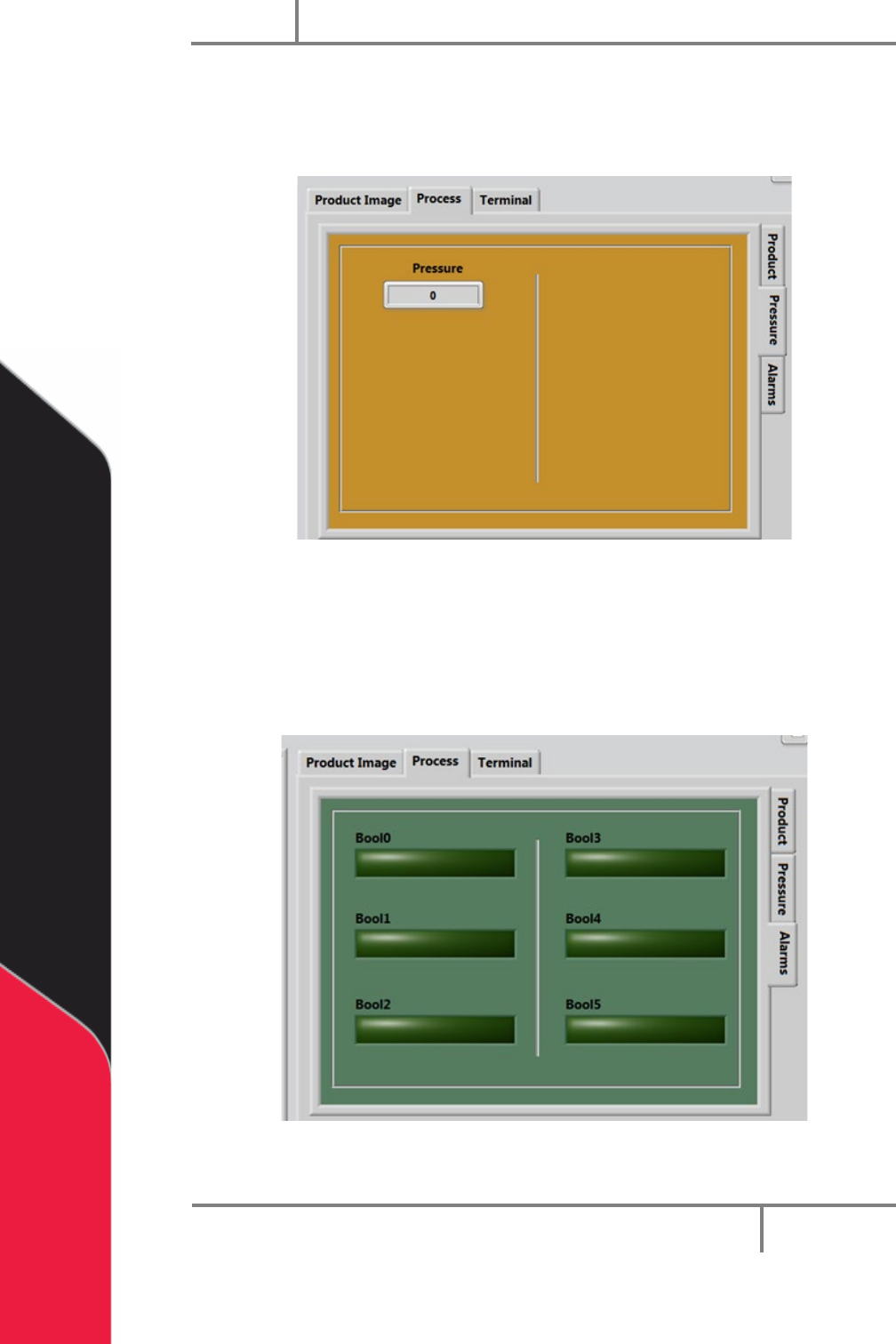
9.2.2 Process Pressure
The Pressure tab is on the right side of the system tabs screens under the Process tab.
This screen shows the process pressure.
Figure 36: Process Pressure Tab
9.2.3 Process Alarms
The Alarms tab will show the operator any preconfigured system faults/warnings. These
alarms are process dependent. Refer to your workcell specific manual for more
information.
Figure 37: Process Alarms Tab
Portal
PVA
Revision H (2018)
49 of 93
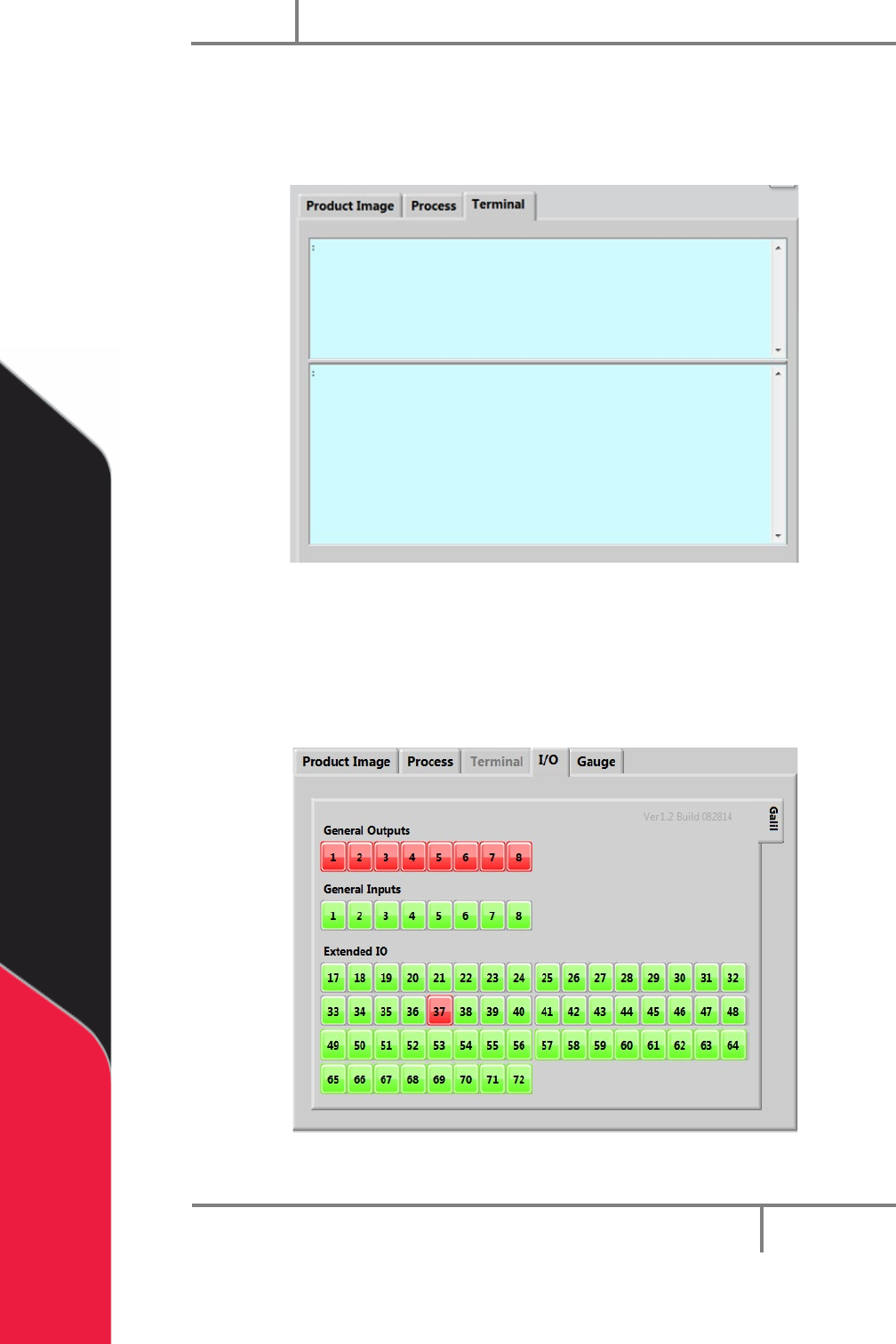
9.3 Terminal
The terminal is used to communicate with the controller. The terminal is used as a
debug tool.
Figure 38: Terminal
9.4 I/O
The outputs can be toggled on and off and inputs can be verified in this window. Refer
to the electrical schematics for I/O designation.
Figure 39: I/O Screen
Portal
PVA
Revision H (2018)
50 of 93
10 Operation
NOTE: You must have administrator privileges to setup and correctly configure
the workcell. Windows
®
User Account Control must be turned off.
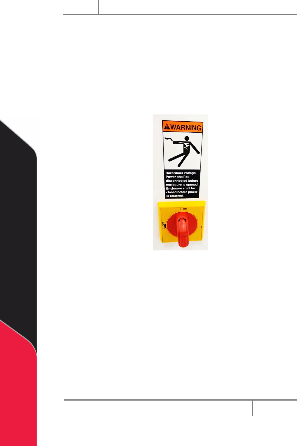
10.1 Startup Procedure
NOTE: Do not power on the workcell, or add material to the pressure vessels
until they are correctly grounded.
1. Turn the main power switch “On”.
Figure 40: Example of a Main Power Switch
2. Make sure the fluid and air pressures are in the correct pressure range.
3. Close all the doors.
4. Turn the DOOR BYPASS key switch to the “OFF” position (If applicable).
5. Engage the “Emergency Stop” button.
6. Turn the main power switch to the “On” position.