TR7600 SIII_Series_Installation_en_v_2_0_2 - 第22页
Test Research, Inc . TR7600 SII I Series U ser Guide – I nstallatio n 12 Figure 20: Adjust the Height of Pads 19) Put the level at the bottom s ide of the m achine and adjust the height o f pads to m ake sure the m achin…
Test Research, Inc.
11 TR7600 SIII Series User Guide – Installation
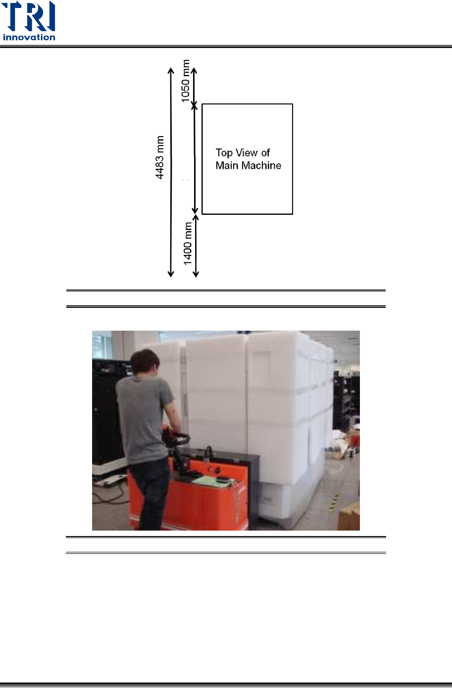
Figure 18: Reserved Space for Daily Operation
Figure 19: Put the Machine In The Right Position
17) Remove the remaining packing materials.
18) Adjust the height of the machine. Please use the fork lift to lift the machine first and then
adjust the height of pads.
2110 mm
Test Research, Inc.
TR7600 SIII Series User Guide – Installation 12
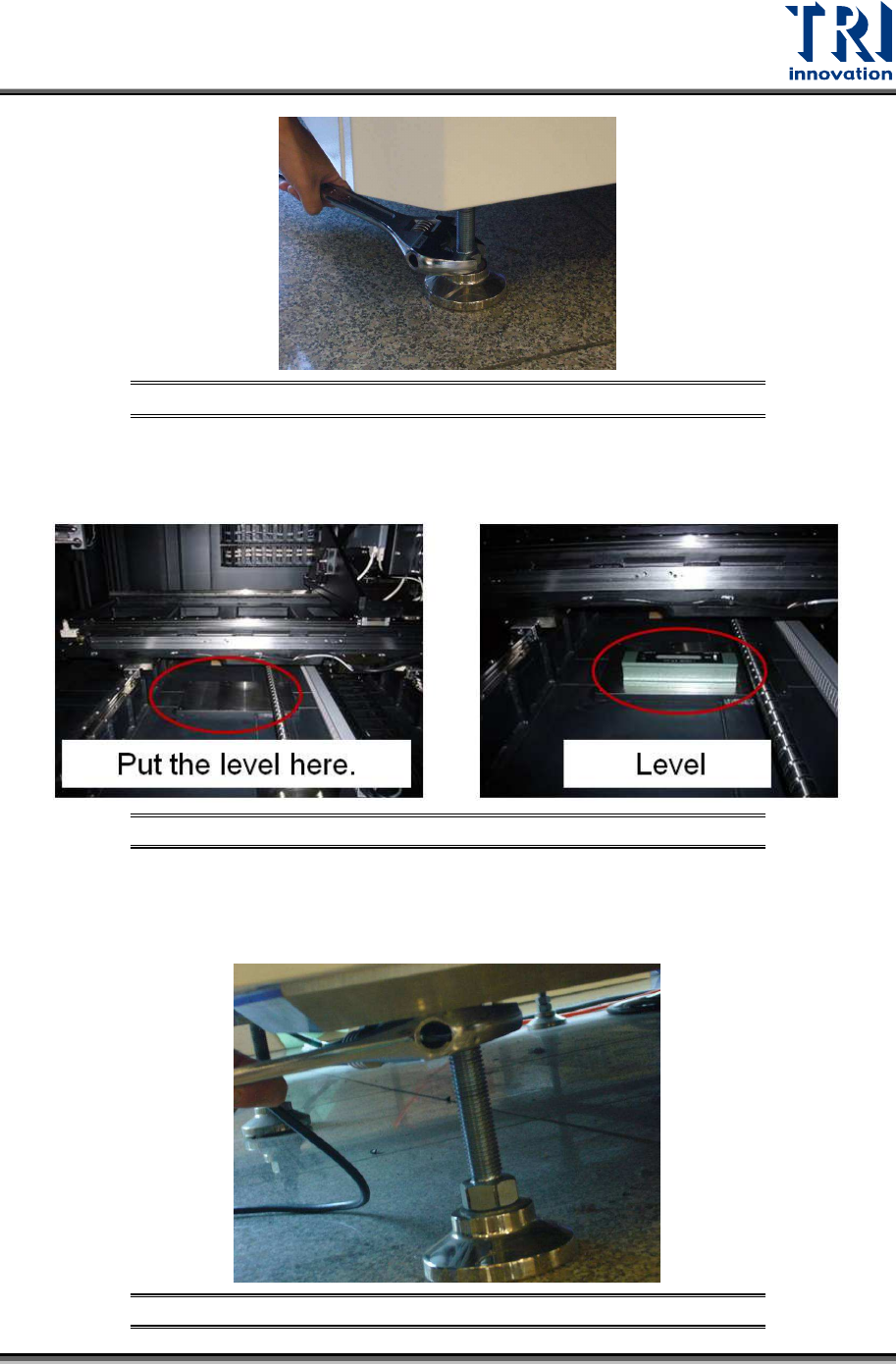
Figure 20: Adjust the Height of Pads
19) Put the level at the bottom side of the machine and adjust the height of pads to make
sure the machine is level.
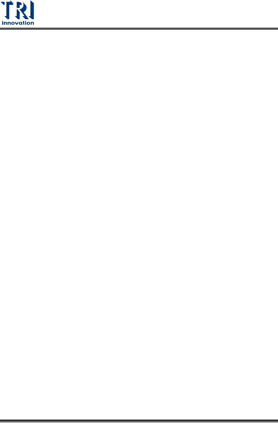
Figure 21: Levelling the Machine
20) After confirming the machine is level at the correct height, you can fasten the nuts
upward to secure the position.
Figure 22: Fasten the Nuts Upward to Secure the Position
Test Research, Inc.
13 TR7600 SIII Series User Guide – Installation
2.3 Check the Accessories
This machine has been thoroughly inspected and tested prior to packing and is ready for
operation. After unpacking carefully, inspect for any damage. If damage is found, file an
immediate claim with the responsible transport service.
The container should contain the following items:
1) Main machine
2) Basic components:
X-Ray Tube
Computer
Keyboard
Mouse
Monitor
Accessories box.
3) After unpacking, you should count the accessories to confirm if the shipping contents are
correct.
2.4 Uninstall Mounting Brackets
1) Open the front door and uninstall the X-Y table mounting brackets. Please keep the
screws with the brackets and do not screw them back to the machine.
Note: Dismantled brackets, screws and gaskets should be kept so that these items
can be used next time when the system needs to be moved.
2) From the front view of the machine, you can see the items listed below.
2 mounting brackets on the lower X axis.
1 mounting bracket (the connection end) on the lower Y axis.
2 mounting brackets on the lower Y axis.
12 hexagonal screws (M6x16 NI) and 20 gaskets (M6 NI 6.4x12x1.6) with these
mounting brackets.
Please uninstall all of them. Keep the screws and gaskets with the brackets and do not
screw them back to the machine.