TR7600 SIII_Series_Installation_en_v_2_0_2 - 第26页
Test Research, Inc . TR7600 SII I Series U ser Guide – I nstallatio n 16 2.5 Install X-ray Tube 1) C arefully remove the X-ray tube from it s pa ck ing carton. A void dropping or bumping the unit. Figure 27: X-Ray Source…
Test Research, Inc.
15 TR7600 SIII Series User Guide – Installation
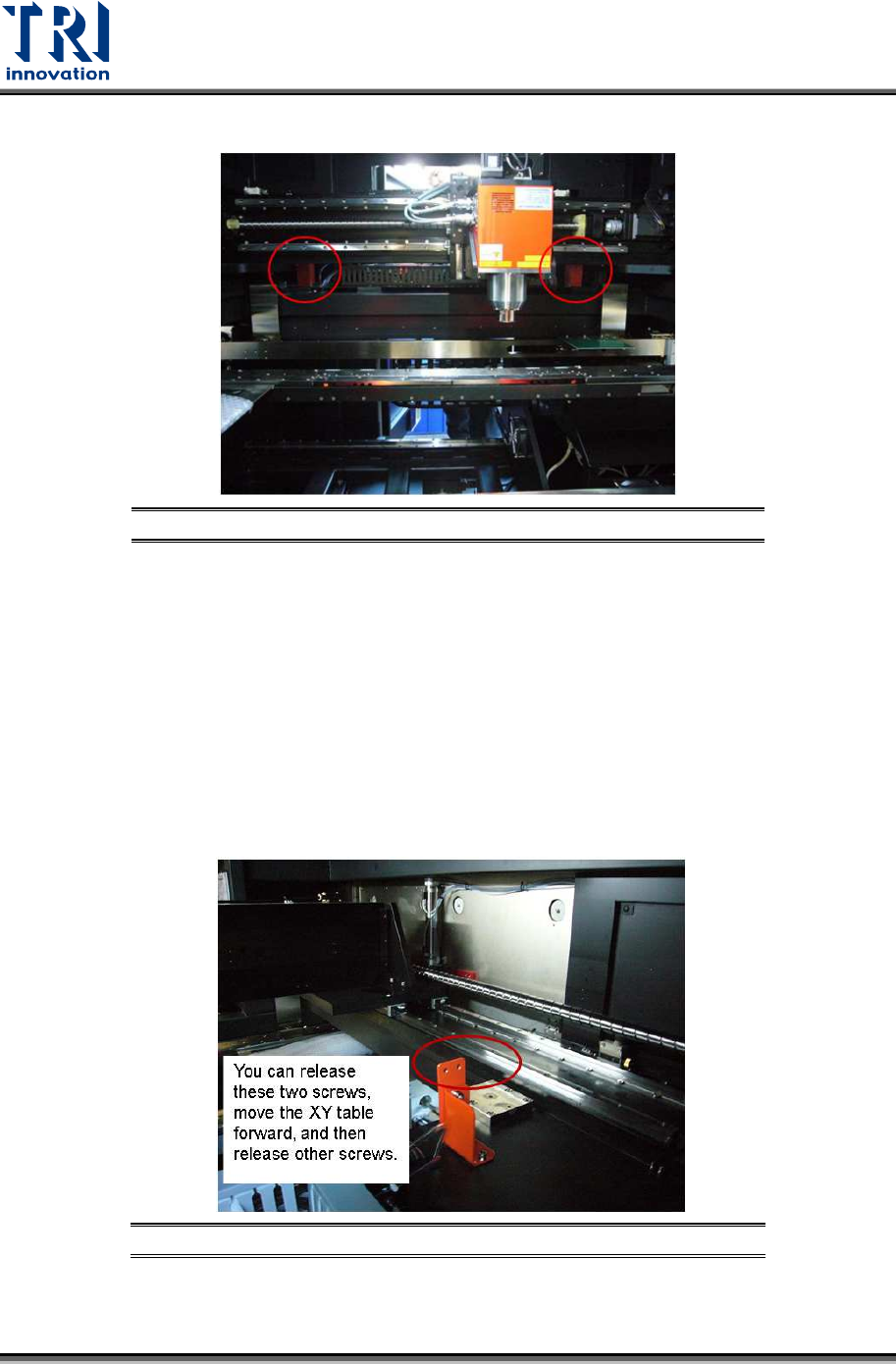
4) Uninstall the mounting brackets of the upper X-Y table.
Figure 25: Uninstall Mounting Brackets
5) From the rear view of the machine, you can see the items listed below.
1 mounting bracket on the tube X axis.
2 types of brackets on the lower Y axis. Each bracket type has 2 pieces.
2 types of
hexagonal screws. One type has 4 hexagonal screws (M5x12 NI) and the
other type has 12 hexagonal screws (M6x16 NI).
2
types of gaskets
. One type has 4 gaskets (M5 NI 5.3x10x1) and the other type
has 12 gaskets (M6 NI 6.4x12x1.6).
Please uninstall these items. Keep the screws and gaskets with the brackets and do not
screw them back to the machine.
Figure 26: Release These Two Screws First
6) There are a total of 10 mounting brackets and 36 screws and 36 gaskets. Please put
them in a plastic bag and keep them for future use.
Test Research, Inc.
TR7600 SIII Series User Guide – Installation 16
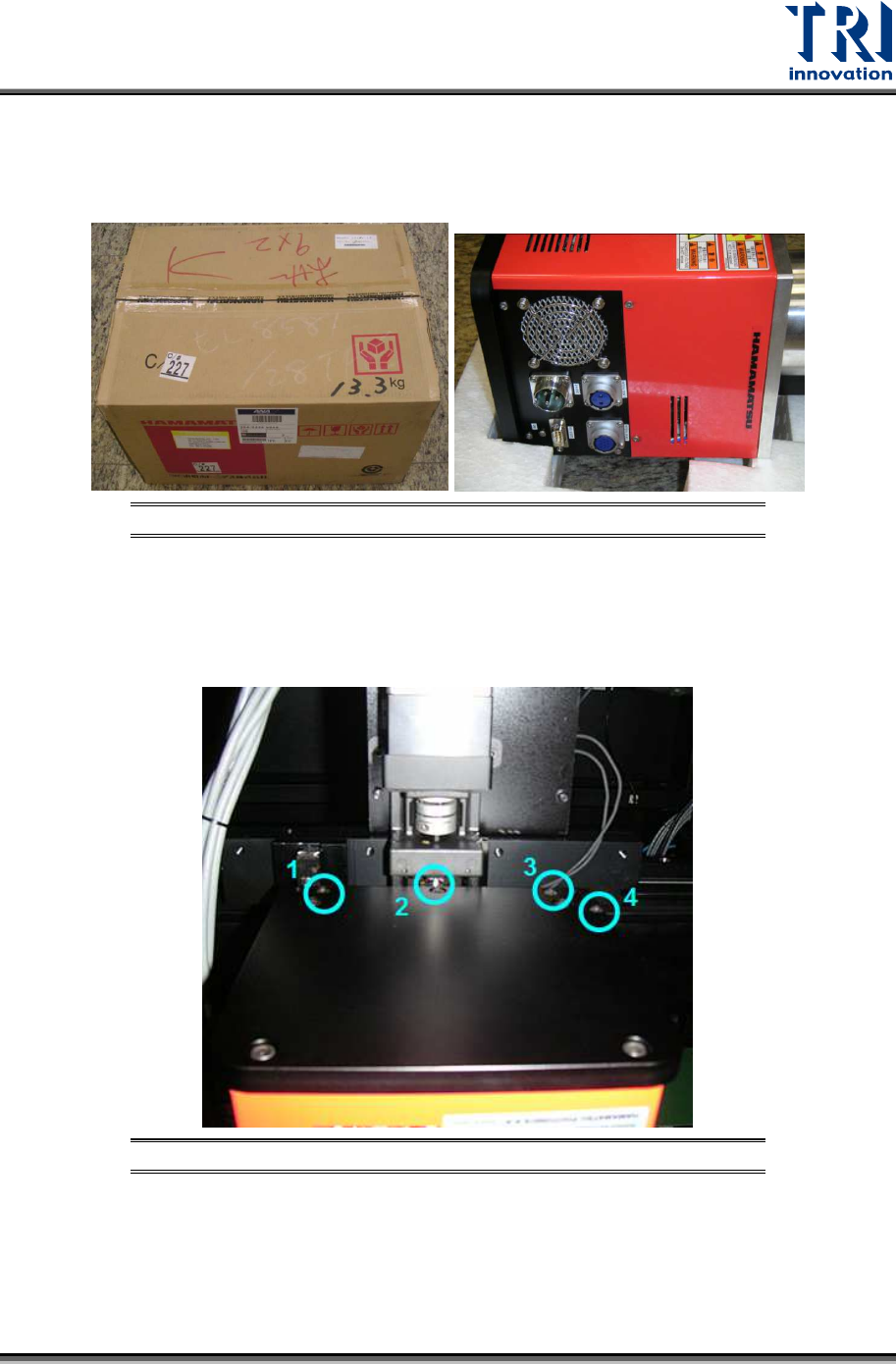
2.5 Install X-ray Tube
1) Carefully remove the X-ray tube from its packing carton. Avoid dropping or bumping the
unit.
Figure 27: X-Ray Source
2) Mount the X-ray tube on the upper X-Y table. Sockets on the X-ray tube should face the
left side of the machine.
3) Fasten the four screws shown in the figure below.
Figure 28: X-Ray Tube Screws
4) Connect the system cables to the tube’s sockets.
Test Research, Inc.
17 TR7600 SIII Series User Guide – Installation
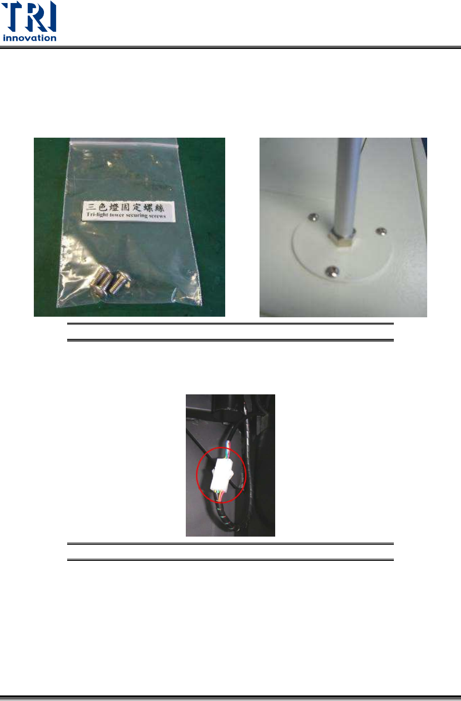
2.6 Install Three-Color Signal Tower
The signal tower should be installed on the top of the machine.
1) Remove the light tower from the accessory box.
2) Fasten these three screws tightly to install the signal tower.
Figure 29: Install the Signal Tower
3) Link the internal socket. Connect the cable of the light tower and the reserved socket
inside the machine.
Figure 30: Connect the Internal Socket