TR7600 SIII_Series_Installation_en_v_2_0_2 - 第28页
Test Research, Inc . TR7600 SII I Series U ser Guide – I nstallatio n 18 2.7 Install A ir Suppl y Hose 1) C onnect the ai r supply hose to the machine. 2) C heck if the pressure o f the air control valve is above 0.5 M P…
Test Research, Inc.
17 TR7600 SIII Series User Guide – Installation
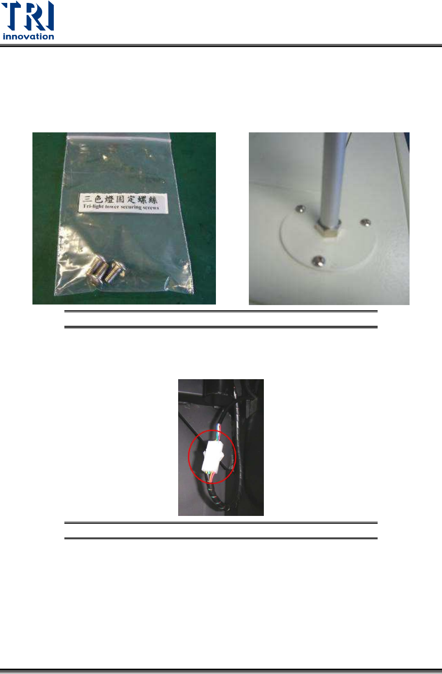
2.6 Install Three-Color Signal Tower
The signal tower should be installed on the top of the machine.
1) Remove the light tower from the accessory box.
2) Fasten these three screws tightly to install the signal tower.
Figure 29: Install the Signal Tower
3) Link the internal socket. Connect the cable of the light tower and the reserved socket
inside the machine.
Figure 30: Connect the Internal Socket
Test Research, Inc.
TR7600 SIII Series User Guide – Installation 18
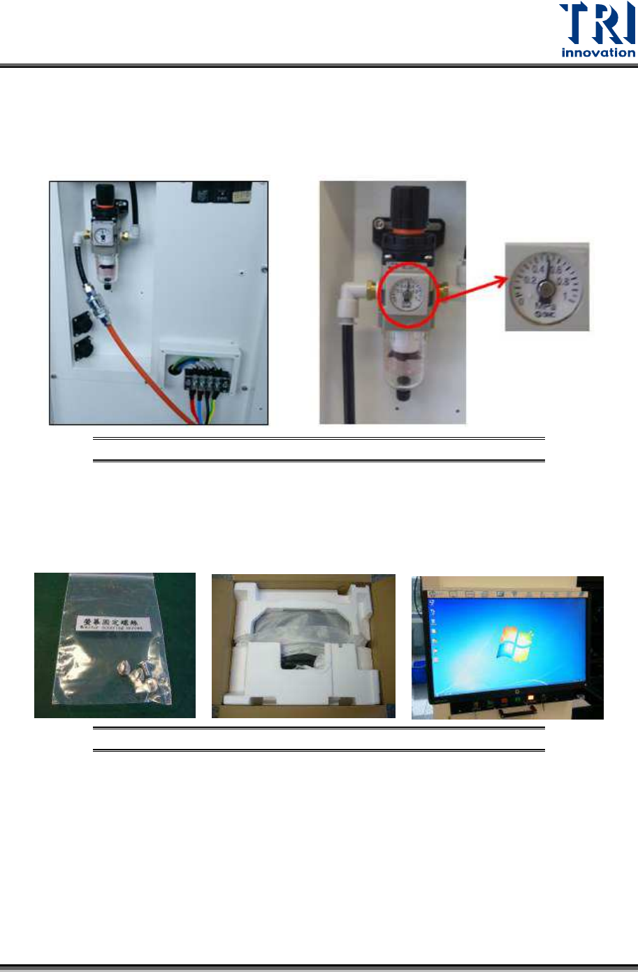
2.7 Install Air Supply Hose
1) Connect the air supply hose to the machine.
2) Check if the pressure of the air control valve is above 0.5 MPa and below 1 MPa.
Figure 31: Check Air Pressure
2.8 Install Monitor
1) Fasten these screws below to install the monitor.
Figure 32: Install the Monitor
Test Research, Inc.
19 TR7600 SIII Series User Guide – Installation
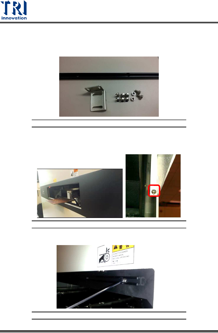
2.9 Datalogic Barcode Installation
The barcode scanner accessories include M5 screw *2, M5 hex screw *2, M4 flat head
screw*6, aluminum support *1, and position adjustment sheet*1
.
Figure 33: Barcode Scanner Accessories
Please follow the steps below to set up the barcode scanner.
1) Loosen the screws on the conveyor cover and take out the cover.
Figure 34: Barcode Scanner Accessories
2) Fasten the aluminum sheet on the inner conveyor frame.
Figure 35: Fixing Datalogic Barcode Aluminum Sheet