TR7600 SIII_Series_Installation_en_v_2_0_2 - 第30页
Test Research, Inc . TR7600 SII I Series U ser Guide – I nstallatio n 20 3) Put bolts into al um inum track. Figure 36 : Puttin g Bolts into the Track 4) Set barcode scanner on th e position adjustment sheet. Figure 37: …
Test Research, Inc.
19 TR7600 SIII Series User Guide – Installation
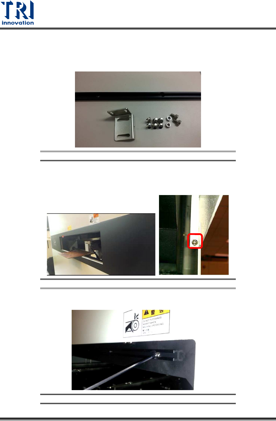
2.9 Datalogic Barcode Installation
The barcode scanner accessories include M5 screw *2, M5 hex screw *2, M4 flat head
screw*6, aluminum support *1, and position adjustment sheet*1
.
Figure 33: Barcode Scanner Accessories
Please follow the steps below to set up the barcode scanner.
1) Loosen the screws on the conveyor cover and take out the cover.
Figure 34: Barcode Scanner Accessories
2) Fasten the aluminum sheet on the inner conveyor frame.
Figure 35: Fixing Datalogic Barcode Aluminum Sheet
Test Research, Inc.
TR7600 SIII Series User Guide – Installation 20
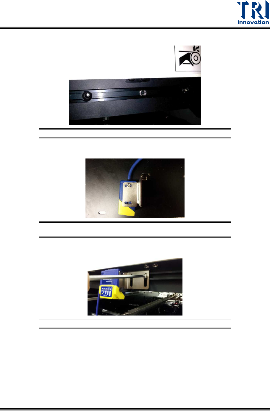
3) Put bolts into aluminum track.
Figure 36: Putting Bolts into the Track
4) Set barcode scanner on the position adjustment sheet.
Figure 37: Tightening the Screws between Position Adjustment Sheet
and Extension Mechanism
5) Fix position adjustment sheet on the slider by M5 screws.
Figure 38: Fixing Position Adjustment Sheet on the Slider
Test Research, Inc.
21 TR7600 SIII Series User Guide – Installation
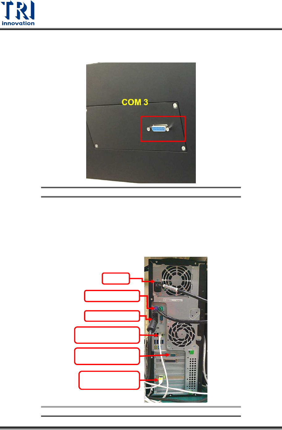
6) Connect the barcode scanner cables COM 3 is at left side, COM 4 is at right side, user
only need to connect the cable to the left blue port. This com port integrates both signal
cable and power cable.
Figure 39: Connecting All the Barcode Scanner Cables
2.10 Repair Station Installation
Repair station system includes a main PC, LCD monitor keyboard, mouse, hand-held
barcode scanner and cross over internet cables.
3) Install repair station system.
Figure 40: The Connection of Repair Station
Power
Keyboard/Mouse
Monitor Cable
The 1st Internet Port
(Connect to Main PC)
RS232 Hand-held Barcode
Scanner
The 2nd Internet Port,
(Connect to Internet)