TR7600 SIII_Series_Installation_en_v_2_0_2 - 第33页
Test Research, Inc . 23 TR7600 SIII Ser ies User G uide – Ins tallation Figure 43: Loader and Unloader Cable 2.11.2 Linking with Unloader SMEMA C onnection s PORT2 – DOWN LINE X98 Black (1) / Green (2) Ready Y106 Red (3)…
Test Research, Inc.
TR7600 SIII Series User Guide – Installation 22
4) Install hand-held barcode scanner. Please connect the signal cable to the
communication port in repair station PC and connect the power supply cable to the plug
with 110 / 220V.
5) Connect AXI system and repair station PC by internet cable.
2.11 Input/Output Signal Port (SMEMA)
2.11.1 Linking with Loader
SMEMA Connections:
PORT1
–
UP LINE
Y104
Black (1) / Green (2) Ready
X
2
A
Red (3) / Blue (4) Board Available
X
2
B
Yellow (5) / White (6) Spare
Figure 41: Loader Socket Position
Located below the power supply socket in the back of the equipment is I/O PORT1. Connect
the connector, and match three sets of different colored wire pairs at the other end of the
cable with the Loader according to its specifications. The three wire pairs are: Black-Green
(Y104) for requesting board from Loader, Red-Blue (X2A) reserved INPUT connector and the
Yellow-White (X2B) reserved INPUT connector. Connect the Black-Green connector to the
Loader Board Request connection. (We use the standard SMEMA signal. If this is different
due to differences in manufacturer, contact the front stage manufacturer to acquire the
connection data.)
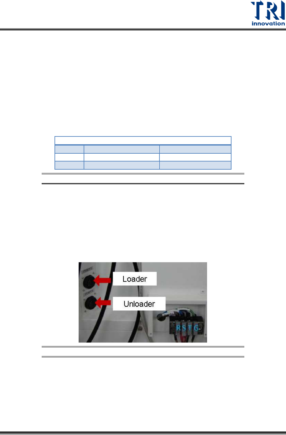
Figure 42: Loader and Unloader Socket Position
Test Research, Inc.
23 TR7600 SIII Series User Guide – Installation
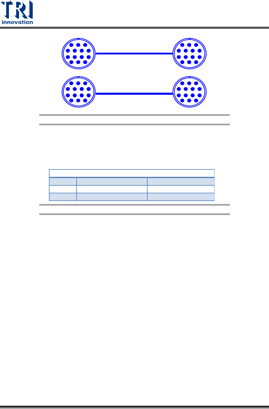
Figure 43: Loader and Unloader Cable
2.11.2 Linking with Unloader
SMEMA Connections
PORT2
–
DOWN LINE
X98
Black (1) / Green (2) Ready
Y106
Red (3) / Blue (4)
Board Available
Y105
Yellow (5) / White (6) OK: Short; NG: Open
Figure 44: Unloader Socket
Located below the power supply socket in the back of the equipment is I/O PORT2. Connect
the connector, and match three sets of different colored wire pairs at the other end of the
cable with the Unloader according to its specifications. The three pairs are: Black-Green
(X98) for receiving READY board request signal from the Unloader, Red-Blue (Y106) for
sending board unload signal to the Unloader and the Yellow-White (Y105) TEST PASS
signal connector. Connect the Black-Green connector with the Unloader’s connector for
sending READY board request signal. Then connect the Yellow-White connector with the
Unloader's connector for receiving TEST PASS signal. (We use the standard SMEMA signal.
If this is different due to differences in manufacturer, contact the rear stage manufacturer to
acquire the connection data.)
PIN1~PIN6
1 2 3
4 5 6 7
8 9 10 11
12 13 14
PIN1~PIN6
1 2 3
4 5 6 7
8 9 10 11
12 13 14
1 2 3
4 5 6 7
8 9 10 11
12 13 14
1 2 3
4 5 6 7
8 9 10 11
12 13 14
Test Research, Inc.
TR7600 SIII Series User Guide – Installation 24
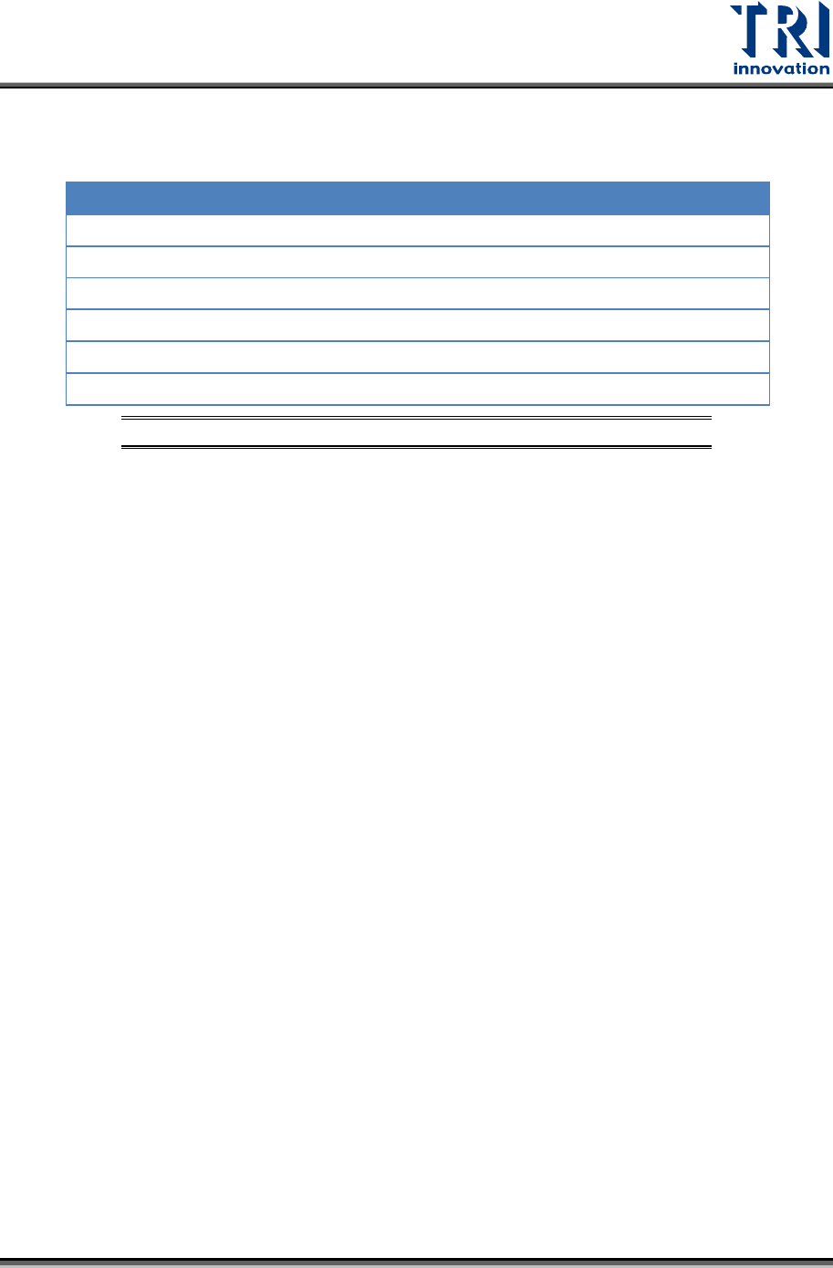
2.12 Working Environment
The Operating and Storage environmental parameters are listed in the following table.
Operating Storage
Ambient Temperature:
0-40°C (32-104°F) -40-66°C (-40-151°F)
Max. Temperature Gradient:
10°C/hour (18°F/hour) 10°C/hour (18°F/hour)
Relative Humidity:
20-80% non-condensing Up to 95% non-condensing
Max. Humidity Gradient:
10%/hour 10%/hour
Max. Wet Bulb Temperature:
25°C (77°F) 46°C (115°F)
Max. Dew Point Temperature:
2°C (36°F) 2°C (36°F)
Figure 45: Operating & Storage Environment for TR7600 SIII