OM-1078-002.pdf - 第101页
• Pointing Device Operation [Center 1-Pt.] Button A crosshair appears on the "Recognition" window . Adjust the crosshair to the pick-up point, using the pointing device. (1) When the [ENABLE] button on the oper…
• Teaching Operation for Alignment of Component Center with
Vacuum Nozzle Center
Perform this teaching operation when no regulation is given to the
shape of components and positioning should be made simply to the
component center.
The teaching operation must be performed with "All Beam
Zero" being displayed.
(1) Follow the teaching procedure below to perform the teaching op-
eration on the component center position.
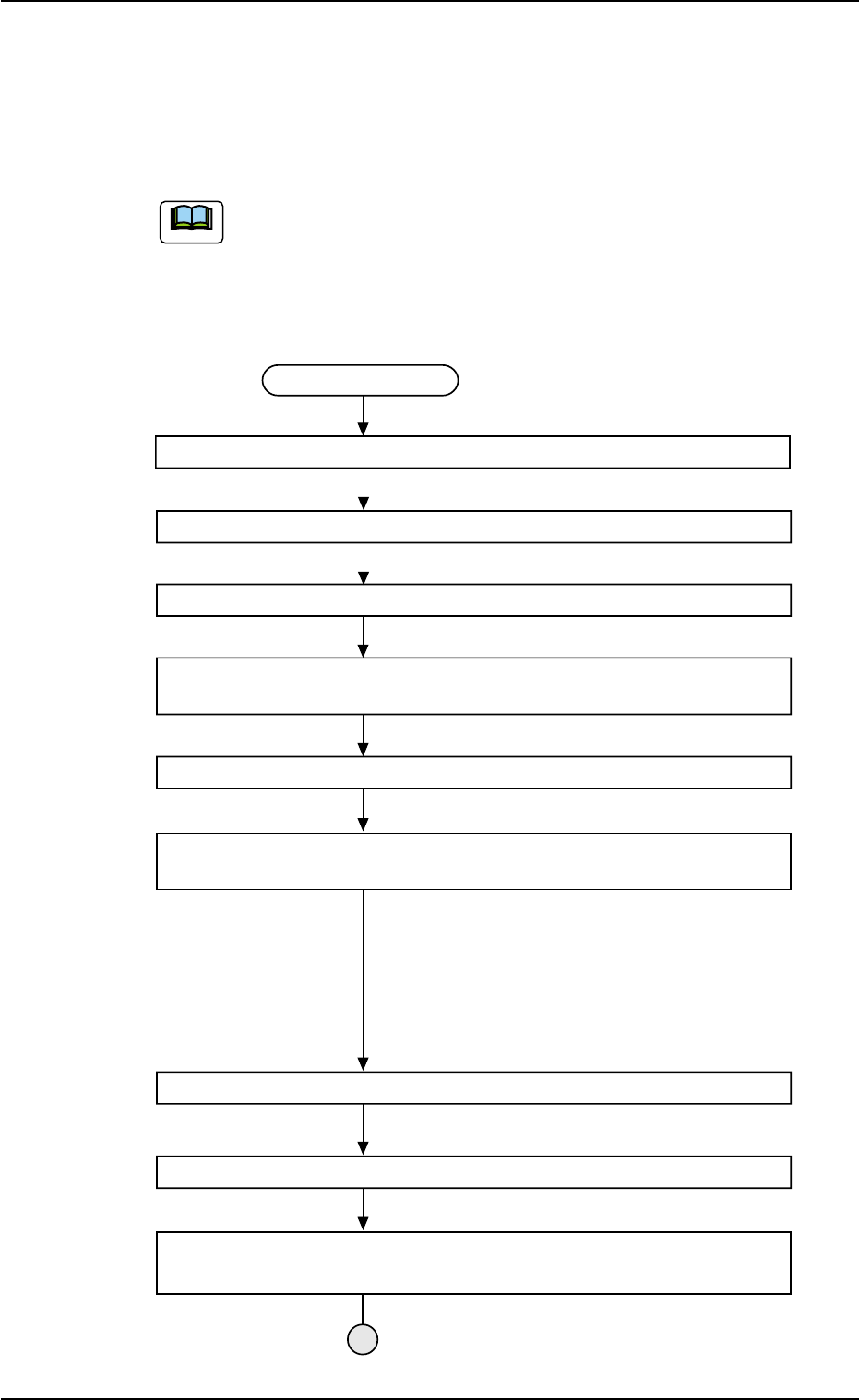
Teaching Procedure
Select the [Tray Teach Pick-Up Pos. [Comp. Center Pos.] button in Fig. B10.
Selection of Head
Setting of Objective Feeder No. for Teaching
Refer to "5.3.6 "Feeder No. Set" Sheet" for details.
Select the [Center 1-Pt.], [1Point], or [2Point] button in "Position" group box
according to the component size.
Select the [Teach Pick-Up Pos. [Comp. Center Pos.]] button.
Press the [ENABLE] button on the operation panel in 2 seconds after the
[ON] button (entitled "MOVE").
The placement head moves to the objective
feeder position for teaching and the image of the pick-up
position is captured by the P.E.C. camera.
In the case of "Center 1-Pt.", the graphic alignment with
the designeted nozzle is made together to facilitate the
manual alignment operation with the pointing device.
Positioning Operation with Pointing Device
Refer to "Pointing Device Operation" (described later) for
details.
Selection of [End] Button
Selection of [YES] Button in "Confirmation" Dialog Box for Replacement of
Offset Data
Fig. B14
0311-002 2-27
AHI01EGP
5.3 "TEACHING" Window (Submenu)
Note
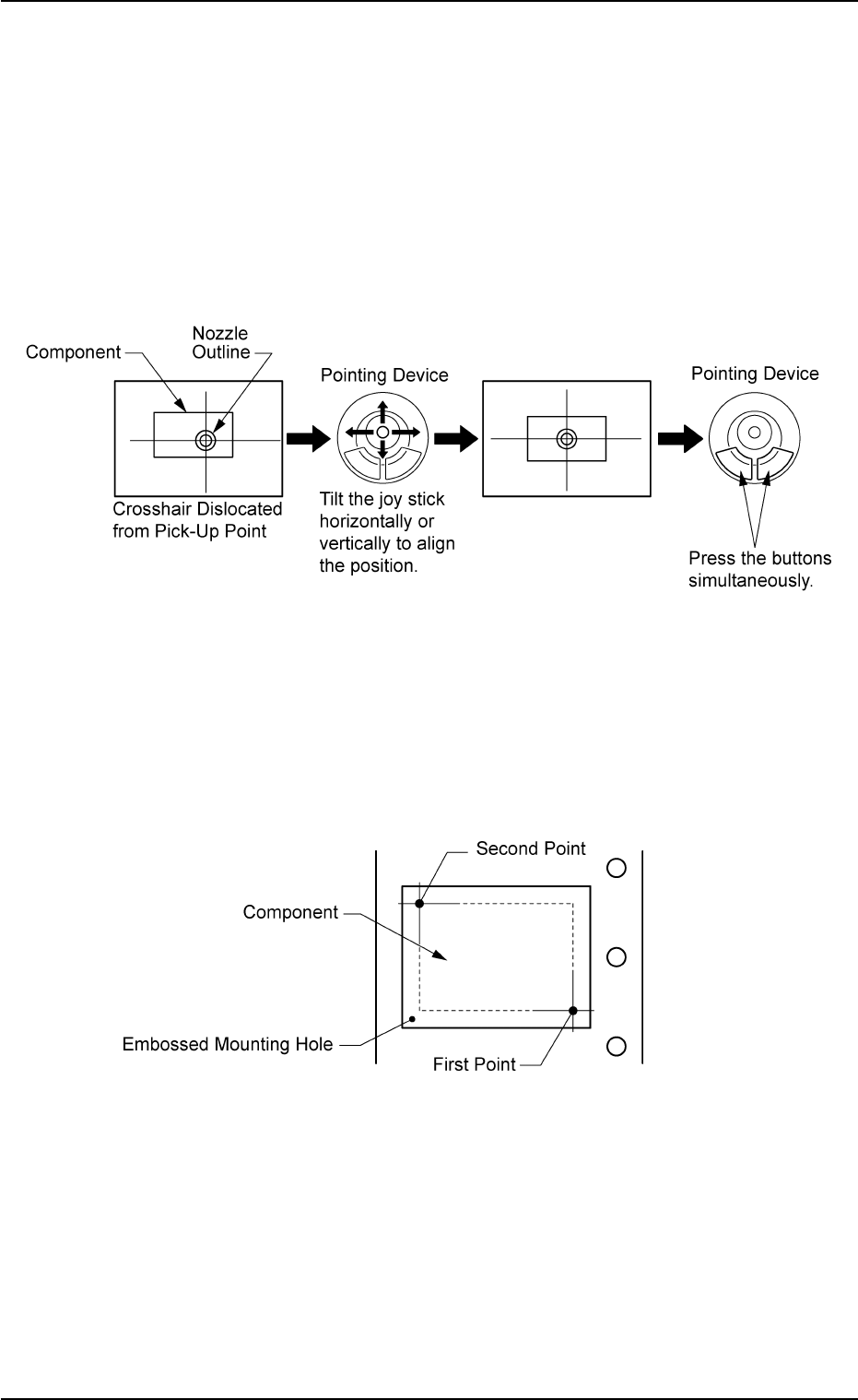
• Pointing Device Operation
[Center 1-Pt.] Button
A crosshair appears on the "Recognition" window.
Adjust the crosshair to the pick-up point, using the pointing device.
(1) When the [ENABLE] button on the operation panel is pressed in 2
seconds after the [Center 1-Pt.] button and the [ON] button (en-
titled "MOVE"), the P.E.C. recognition camera moves to the des-
ignated feeder No. position.
(2) Manipulate the pointing device as shown below.
Fig. B15
[1Point] and [2Point] Buttons
Specify two edges of the component to be picked up or the embossed
mounting hole.
Specify two edges in the embossed area of the component.
Or, specify two corner points in the embossed mounting hole.
Fig. B16
(1) When the [ENABLE] button on the operation panel is pressed in 2
seconds after the [1Point] button and the [ON] button (entitled
"MOVE"), the P.E.C. recognition camera moves to the specified
feeder No. position.
A crosshair (First Point) appears on the "Recognition" Window.
0204-001 2-28
AHI01EGP
5.3 "TEACHING" Window (Submenu)
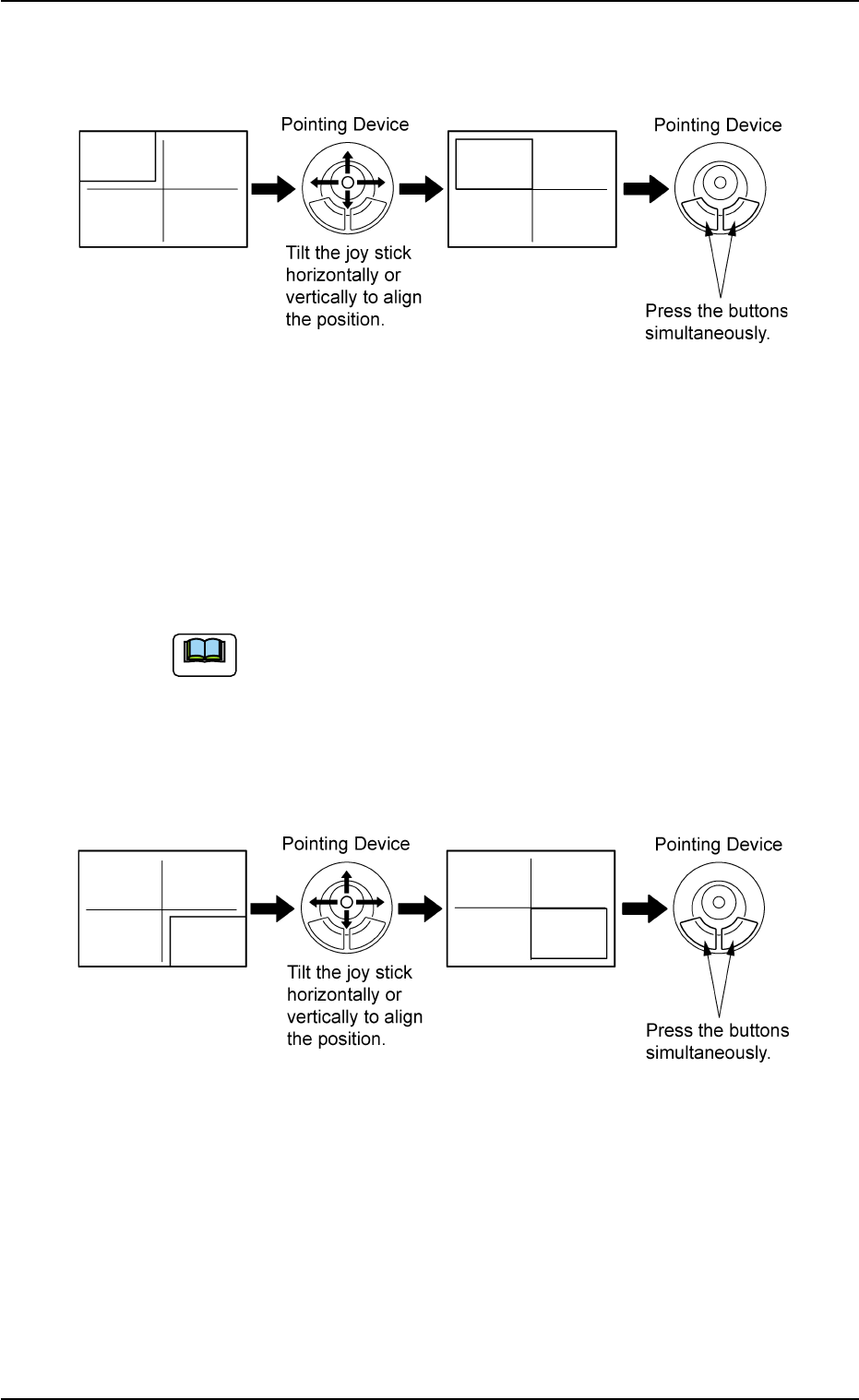
(2) Make an alignment with the pointing device and press the right
and left buttons simultaneously.
Fig. B17
(3) When the [ENABLE] button on the operation panel is pressed in 2
seconds after the [2Point] button and the [ON] button (entitled
"MOVE"), the P.E.C. recognition camera moves to the specified
feeder No. position.
A crosshair (Second Point) appears in the "Recognition" window.
When the [ON] button (entitled "MOVE") is hidden behind
the recognized image, touch the image softly to make it
disappear and press the [ON] button.
(4) Make an alignment with the pointing device and press the right and
left buttons simultaneously.
Fig. B18
0311-002 2-29
AHI01EGP
5.3 "TEACHING" Window (Submenu)
Note