OM-1078-002.pdf - 第113页
*5 [T ray Unit Adj.] Button When this button is pressed, the "T ray Unit Adj." sheet appears. *6 [Clear Adj.] Button When this button is pressed, the following "Confirmation" dialog box opens. Fig. B2…

*3 "Mode" Group Box
Various actions can be selected.
The following buttons are provided in this group box.
[All Beam (Incl. NC Axis) Heads Zero] Button
When this button is pressed, all X/Y beams are zeroed.
When the [ENABLE] button on the operation panel is pressed in 2
seconds after this button and the [ON] button (entitled "MOVE"), the
zeroing operation starts.
[Data Pos. Move] Button
When this button is pressed, the X/Y beam moves to the specified
position.
When the [ENABLE] button is pressed on the operation panel in 2
seconds after this button and the [ON] button (entitled "MOVE"), the
X/Y beam moves to the position where the parameters set in the "X
(mm)" and "Y (mm)" data fields of the label "OFFSET" in the com-
ponent library data and the step data are referred to.
[Manual Alignment] Button
When the [MOVE] button is pressed after this button, the pointing
device operation becomes accessible and the manual alignment
operation can be performed.
[Manual Axis] Button
When this button is pressed, the "Manual Axis" sheet appears.
*4 Set Status
When the "P.E.C. Dsbl." or the "Comp. Recognition Dsbl." check
box in the "Test Run" tab sheet is turned on (checked), the back-
ground color of "Recognition Dsbl." turns light red. (No background
color in normal cases).
No recognition processing is made even if a teaching op-
eration is performed when each check box is turned on
(checked) in the "Test Run" tab sheet. Therefore, various
teaching operations will get incorrect results.
When all beams are zeroed completely, the background color of "All
Beam Zero" turns green. Otherwise, the background has no color.
(a) When each section is not set up and a teaching opera-
tion is performed, note that the offset values may not
be taught correctly.
(b) Before performing a teaching operation, be sure to zero
all beams.
0311-002 2-39
AHI01EGP
5.3 "TEACHING" Window (Submenu)
Note
Note
*5 [Tray Unit Adj.] Button
When this button is pressed, the "Tray Unit Adj." sheet appears.
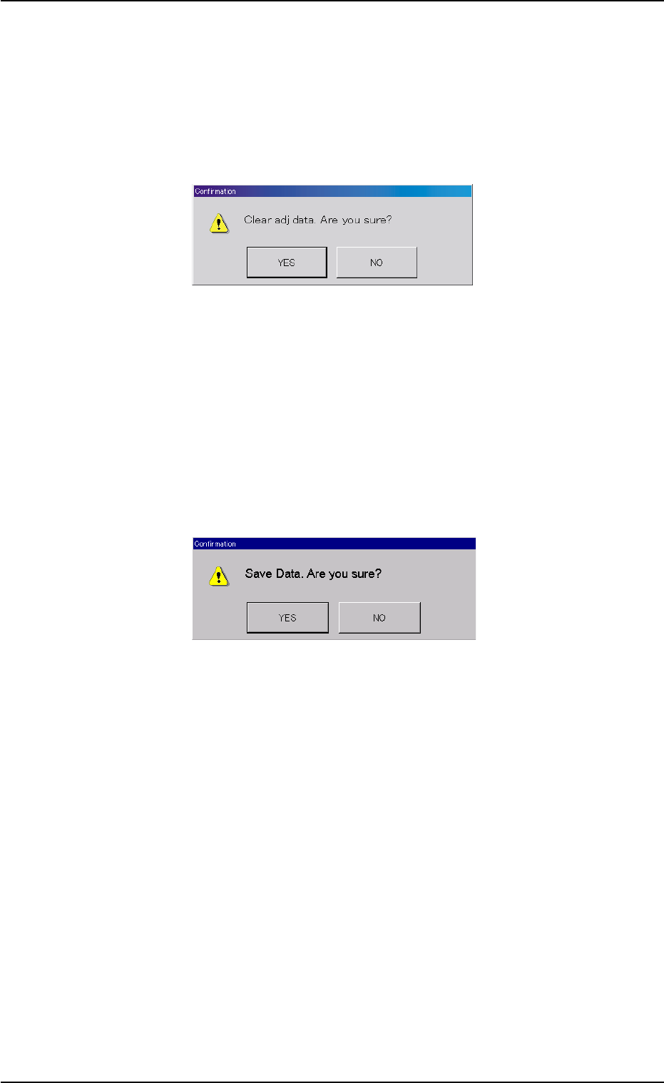
*6 [Clear Adj.] Button
When this button is pressed, the following "Confirmation" dialog box
opens.
Fig. B25
*7 [Cancel] Button
When pressed, this button cancels the results of the teaching op-
eration without reflecting them on the offset data.
*8 [End] Button
When this button is pressed, the following "Confirmation" dialog box
opens.
Fig. B26
When the [YES] button is pressed, the results of the teaching op-
eration are reflected on the offset data and the dialog box closes.
When the [NO] button is pressed, the dialog box closes without re-
flecting the results of the teaching operation on the offset data.
*9 "Control Switch" Group Box
When the [ENABLE] button on the operation panel is pressed in 2
seconds after one of the buttons in the "Mode" group box (*3) and
the [ON] button (entitled "MOVE"), the selected action takes place.
*10 [Return] Button
When this button is pressed, the "Pick-Up Location" sheet appears.
0311-002 2-40
AHI01EGP
5.3 "TEACHING" Window (Submenu)

• Teaching Operation for Settings of Tray Matrix Pitches X and Y,
Side Lengths, and Positional Offsets
(a) Before performing the teaching operation, be sure to con-
firm that correct parameters are set in the "Matrix X" and
"Matrix Y" text boxes of the label "Tray data" in the com-
ponent library data of the pertinent tray.
If incorrect parameters are set, the pitch data cannot be
calculated correctly.
(b) The teaching operation must be performed with "All Beam
Zero" being displayed.
Operation Procedure
(1) Press the [Tray Zeroing Corner] button.
(2) Press the [Data Pos. Move] button.
The P.E.C. recognition camera moves to the specified position.
(3) Confirm that the origin position (tray corner) of the tray is on the
"Recognition" window. Otherwise, press the [Manual Axis] but-
ton for the adjustment.
(4) Press the [Manual Alignment] button and then the [MOVE] but-
ton.
Proceed to the operation of the pointing device and execute the
manual alignment operation.
(5) Press the [Pick-Up First Pos.] button.
(6) After selecting one of the "Position" buttons, press the [Data Pos.
Move] button.
(7) Confirm that the first component in the tray matrix is displayed in
the "Recognition" window. Otherwise, press the [Manual Axis]
button for the adjustment.
(8) Press the [Manual Alignment] button and then the [MOVE] but-
ton.
Proceed to the operation of the pointing device and execute the
manual alignment operation.
Refer to "Pointing Device Operation" in "5.3.3 "Tray Teach Pick-
Up Pos. [Comp. Center Pos.]" Sheet" for details.
(9) Press the [Pick-Up Last Pos.] button.
Follow the same procedure similar to "Pick-Up First Pos." and
perform the teaching operation.
(10) When the [End] button is pressed after the teaching operations
on the three items are completed, it must be determined whether
the taught data should be saved or not.
• When the [YES] button is selected, the data is saved.
• When the [NO] button is selected, the data is not saved.
0311-002 2-41
AHI01EGP
5.3 "TEACHING" Window (Submenu)
Note