OM-1078-002.pdf - 第123页
1.1.2 Composition of Placement Feeder Location Data The set parameters are used to determine which feeder slot Nos. (Fdr . Nos.) various types of components should be allocated to. The allocated component IDs (types) mus…
1. Pattern Program
1.1 Outline of Pattern Program
1.1.1 Outline of Various Data
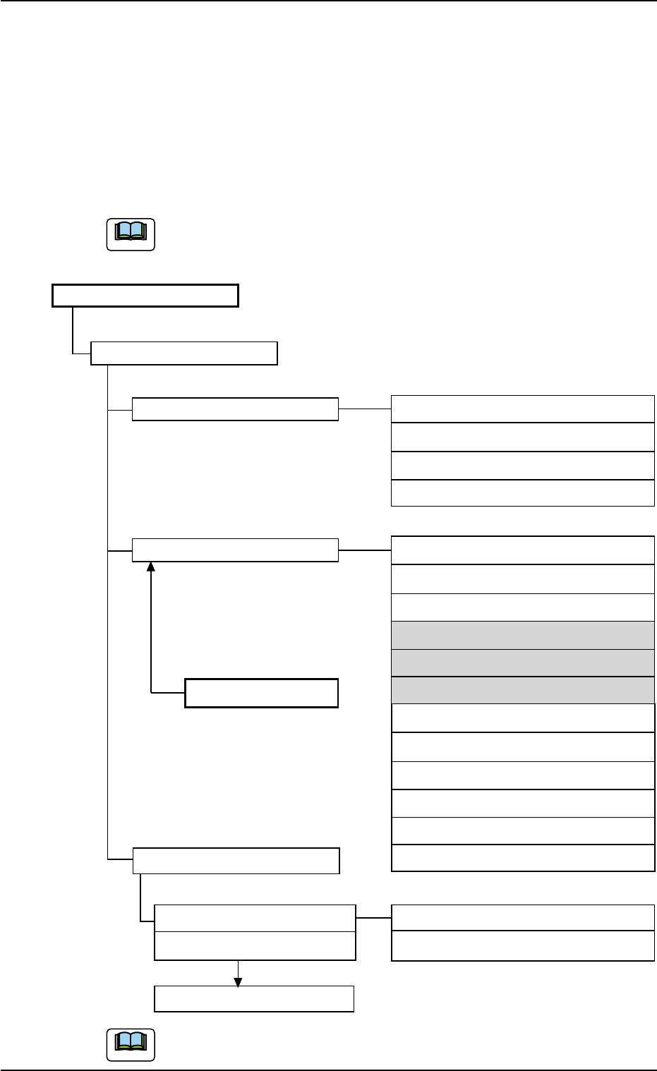
The pattern program is composed of the following data.
The grayed areas are the items related to the multi-layer tray
feeder.
Pattern Program
Pattern Program Name
Operation Data P.C.B. Data (A01)
P.C.B. Recognition Data (A02)
P.C.B. Recognition Mark Data (A03)
Setup Data (A04)
Placement Feeder Location Feeder Base #1 (B01)
Feeder Base #3 (B01)
Feeder Base #4 (B01)
Component ID TRAY #2 F701-F799 (B02)
TRAY #2 F801-F899 (B02)
Component Library TRAY #2 STEP (B03)
FB#3 VIB Feeder #1 (B04)
FB#3 VIB Feeder #2 (B04)
FB#3 VIB Feeder #3 (B04)
FB#4 VIB Feeder #1 (B04)
FB#4 VIB Feeder #2 (B04)
Placement Data FB#4 VIB Feeder #3 (B04)
Placement Data U01 (C01) P Data (C02)
Placement Data U02 (C01) O Data (C03)
Placement Data Un (C01)
(B02) and (B03) show the item Nos. to be referred to.
1. Pattern Program
0311-002 3-2 AHI01EGP
Note
Note
1.1.2 Composition of Placement Feeder Location Data
The set parameters are used to determine which feeder slot Nos. (Fdr.
Nos.) various types of components should be allocated to.
The allocated component IDs (types) must be specified for the multi-
layer tray feeder.
Refer to "2.4 Placement Feeder Location Data" in "Section 2" (the in-
struction manual (Vol. 3: Programming and Machine Data) of the main
machine) for details.
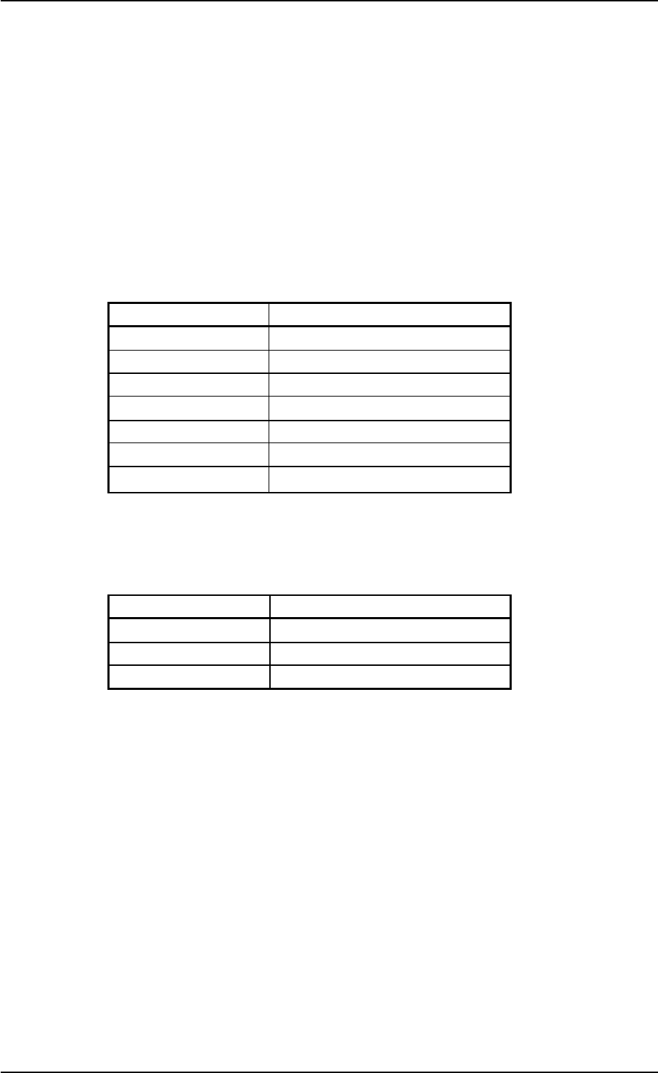
B02 TRAY #2 F701-F799 and TRAY #2 F801-F899
Table C1
Ref. No. Data Name
B02_01 Fdr. No.
B02_02 Component ID
B02_03 C
B02_04 Comment
B02_05 Library Comment
B02_06 Dir [deg], Carrier Data Type
B02_07 Nozzle #1, C, Nozzle #2, C
B03 TRAY #2 STEP
Table C2
Ref. No. Data Name
B03_01 Tray #2 Step No. Offset
B03_02 Step
B03_03 Block 1 through Block 9
1.1 Outline of Pattern Program
0311-002 3-3 AHI01EGP
1.2 Pattern Program
1.2.1 Placement Feeder Location
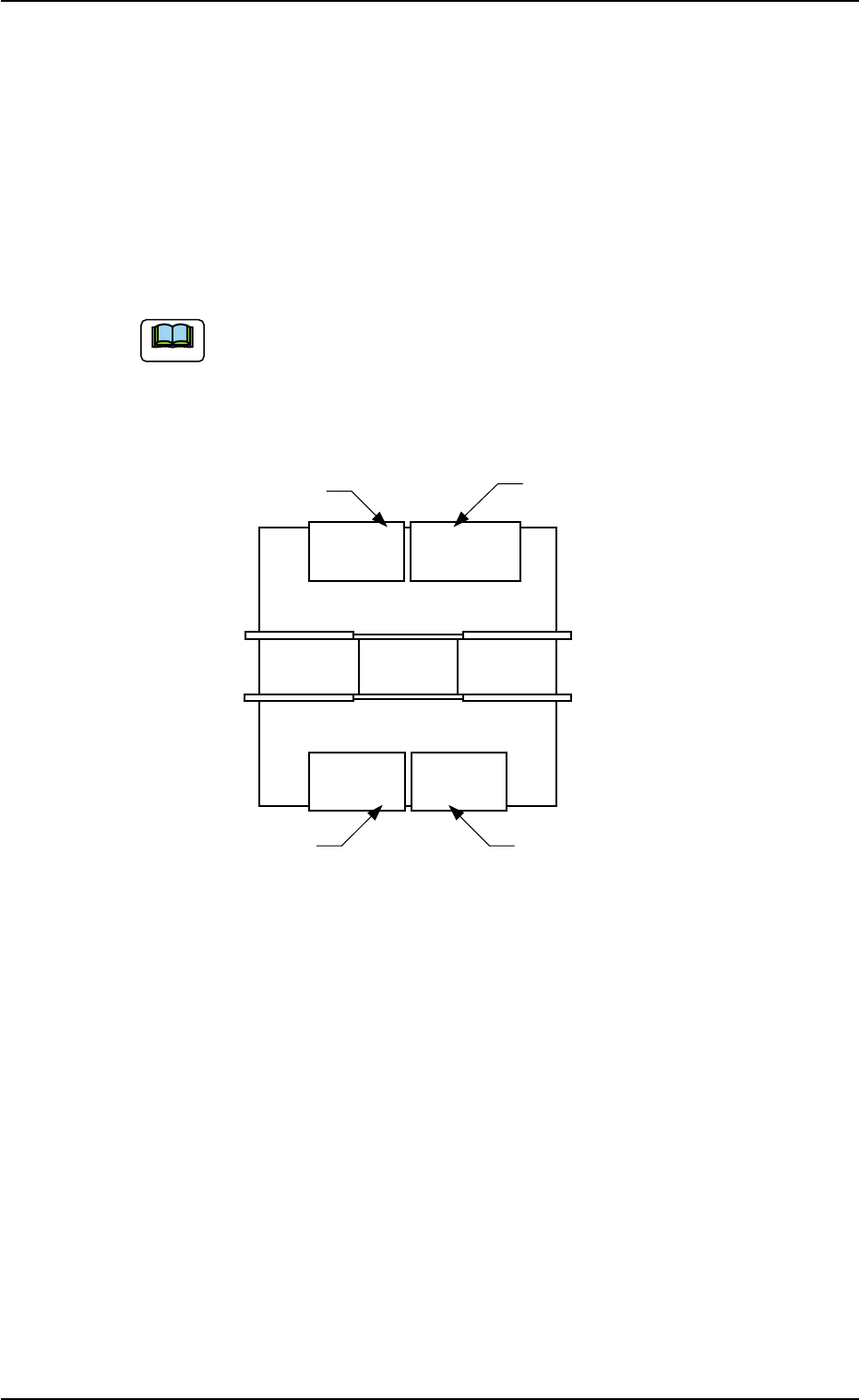
(B02) TRAY #2 F701-F799 and TRAY #2 F801-F899
It can be determined which components must be used and
which feeder No. (Fdr. No.) of the multi-layer tray feeder must
be loaded with the selected components.
The following shows the positional relation between the feeder
bases.
Fig. C1
1.2 Pattern Program
0311-003 3-4 AHI01EGP
Feeder Base #3
(Rear Side of Machine)
Feeder Base #1
Feeder Base #2
(Multi-Layer Tray Feeder)
Feeder Base #4
(Front Side of Machine)
Note