OM-1078-002.pdf - 第127页
(B02_06) Dir [deg], Carrier Data T ype Shown are the values specified in the component library data. (B02_7) Nozzle #1, C, Nozzle #2, C Displayed are the nozzle IDs and control commands speci- fied in the component libra…
The numbers in ( ) indicate the feeder Nos. where the feeder
No. offset in the operation data is added.
(B02_02) Component ID
Set component IDs in the text box.
(B02_03) C
Set control commands in the text box.
- (hyphen): This command handles the steps as those for
the placement feeder location data.
E:This command shows the end of the placement
feeder location data.
The step where "E" is set is valid.
S:This command invalidates the steps specified as
placement feeder location data.
X:This command invalidates the steps specified as
placement feeder location data and shows the end
of the data.
(B02_04) Comment
A comment can be entered for each feeder No. (Fdr. No.).
Up to 32 characters (alphanumerics and marks) can be
used.
(a) The performance of the machine is not affected by these
commands. In other words, it has nothing to do with or
without these comments.
(b) It is recommended to set helpful information on comments
related to the feeder Nos. (Fdr. Nos.).
(B02_05) Library Comment
Displayed is the comment entered in the component library
data.
1.2 Pattern Program
Fig. C6
C
-
Fig. C5
Component ID
C1005T05B0---
Fig. C7
Comment
031 1-002 3-6
AHI01EGP
Note
Note
If a control command other than
the following ones is used, the
step becomes invalid.
CAUTION
Fig. C7-1
Library Comment
(B02_06) Dir [deg], Carrier Data Type
Shown are the values specified in the component library data.
(B02_7) Nozzle #1, C, Nozzle #2, C
Displayed are the nozzle IDs and control commands speci-
fied in the component library data.
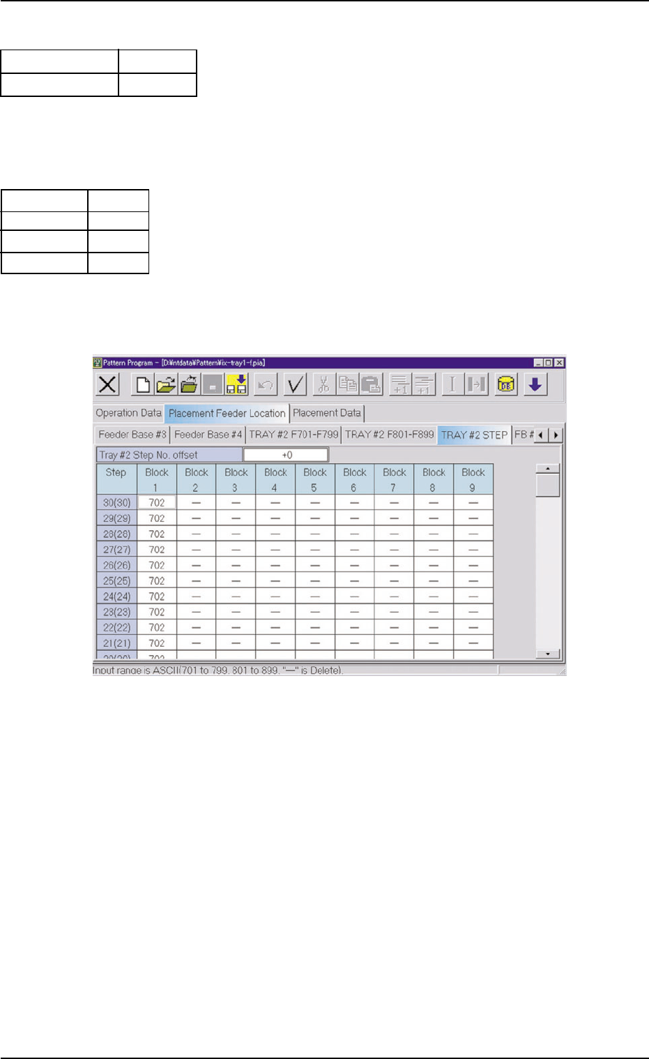
(B03) Tray #2 STEP
Fig. C10
(B03_01) Tray #2 Step No. Offset
Set the offset value for the component allocation to the multi-
layer tray feeder.
The set parameter is added to the step No. designated in
the step data.
(B03_02) Step
Shown are the step Nos. of the rack.
(B03_03) Blocks 1 through 9
Specify what type of components should be set in which
block of which step.
1.2 Pattern Program
0311-002 3-7 AHI01EGP
Embossed
0
Fig. C8
E A06
S
E A04
-
Nozzle #1
C
Nozzle #2
C
Fig. C9
Carrier Data Type
Dir [deg]
1.3 "Placement Feeder Location" Tab
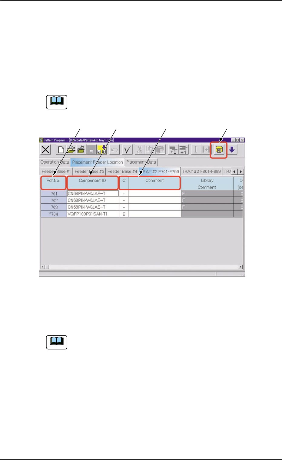
1.3.1 "TRAY #2 F701-F799" Tab
••
••
• Sheet Layout
When the "TRAY #2 F701-F799" tab is pressed in the "Placement
Feeder Location" tab sheet, the following tab sheet appears.
Follow the same procedure to make the "TRAY #2 F801-F899"
tab sheet visible.
Fig. C11 "TRAY #2 F701-F799" Tab Sheet
••
••
• Sheet Composition
Refer to "4.1.3 Basic Usage of Text Boxes" in "Section 2" (the
instruction manual (Vol. 3: Programming and Machine Data) of
the main machine) for the detailed information on how to enter
parameters.
*1 [Component ID List] Icon
When this icon is pressed, the "Component ID List" window opens.
This window enables you to select a component ID from the com-
ponent library and allocate it to an arbitrary feeder (Fdr. No.).
Refer to "4.3.2 "Component ID List" Window" in "Section 2" (the
instruction manual (Vol. 3: Programming and Machine Data) of the
main machine) for details.
1.3 "Placement Feeder Location" Tab
0311-002 3-8 AHI01EGP
*1
*2 *3
*4
Note
Note