OM-1078-002.pdf - 第128页
1 .3 "Placement Feeder Location" T ab 1.3.1 "TRA Y #2 F701-F799" T ab • • • • • Sheet Layout When the "TRA Y #2 F701-F799" tab is pressed in the "Placement Feeder Location" tab she…
(B02_06) Dir [deg], Carrier Data Type
Shown are the values specified in the component library data.
(B02_7) Nozzle #1, C, Nozzle #2, C
Displayed are the nozzle IDs and control commands speci-
fied in the component library data.
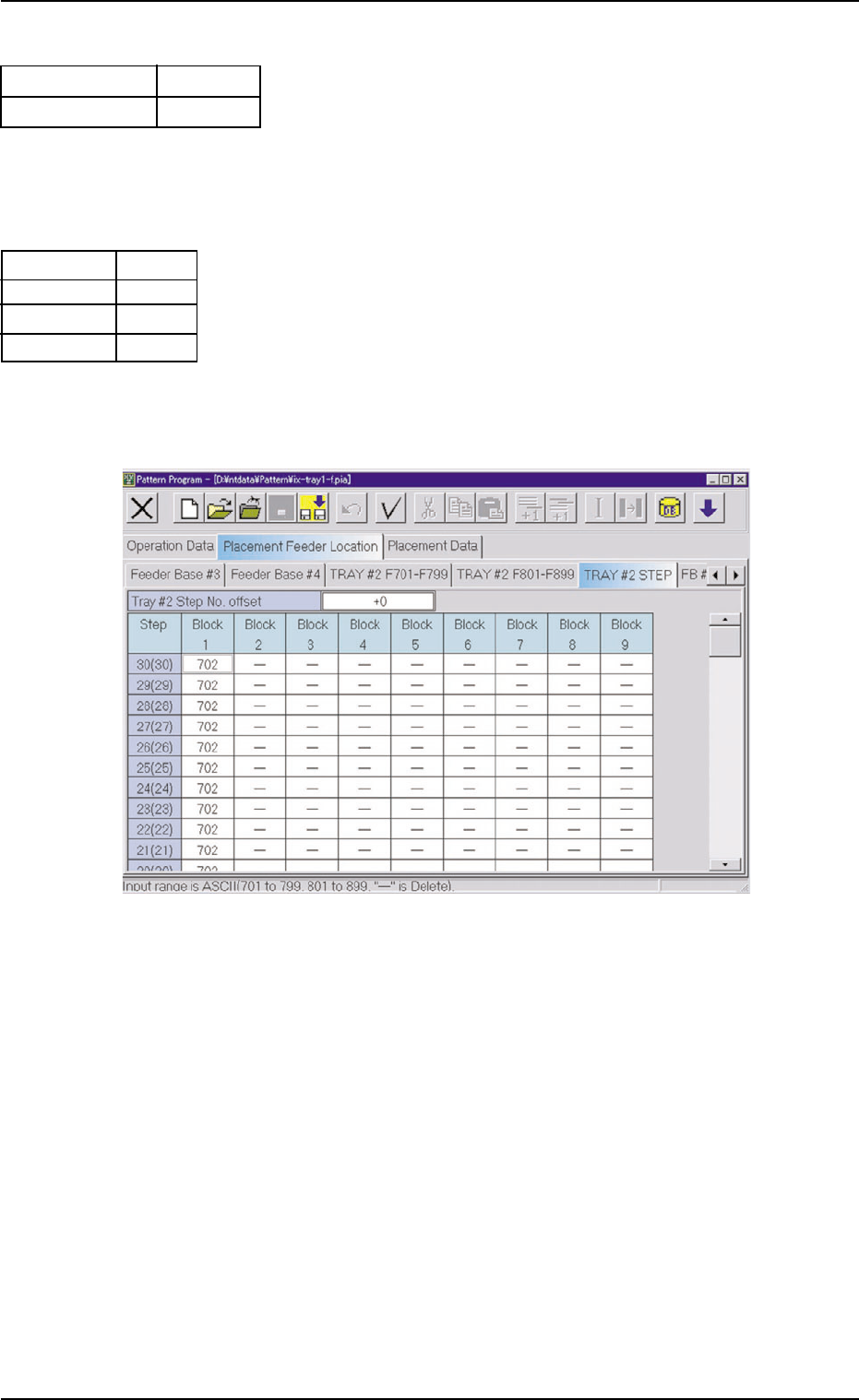
(B03) Tray #2 STEP
Fig. C10
(B03_01) Tray #2 Step No. Offset
Set the offset value for the component allocation to the multi-
layer tray feeder.
The set parameter is added to the step No. designated in
the step data.
(B03_02) Step
Shown are the step Nos. of the rack.
(B03_03) Blocks 1 through 9
Specify what type of components should be set in which
block of which step.
1.2 Pattern Program
0311-002 3-7 AHI01EGP
Embossed
0
Fig. C8
E A06
S
E A04
-
Nozzle #1
C
Nozzle #2
C
Fig. C9
Carrier Data Type
Dir [deg]
1.3 "Placement Feeder Location" Tab
1.3.1 "TRAY #2 F701-F799" Tab
••
••
• Sheet Layout
When the "TRAY #2 F701-F799" tab is pressed in the "Placement
Feeder Location" tab sheet, the following tab sheet appears.
Follow the same procedure to make the "TRAY #2 F801-F899"
tab sheet visible.
Fig. C11 "TRAY #2 F701-F799" Tab Sheet
••
••
• Sheet Composition
Refer to "4.1.3 Basic Usage of Text Boxes" in "Section 2" (the
instruction manual (Vol. 3: Programming and Machine Data) of
the main machine) for the detailed information on how to enter
parameters.
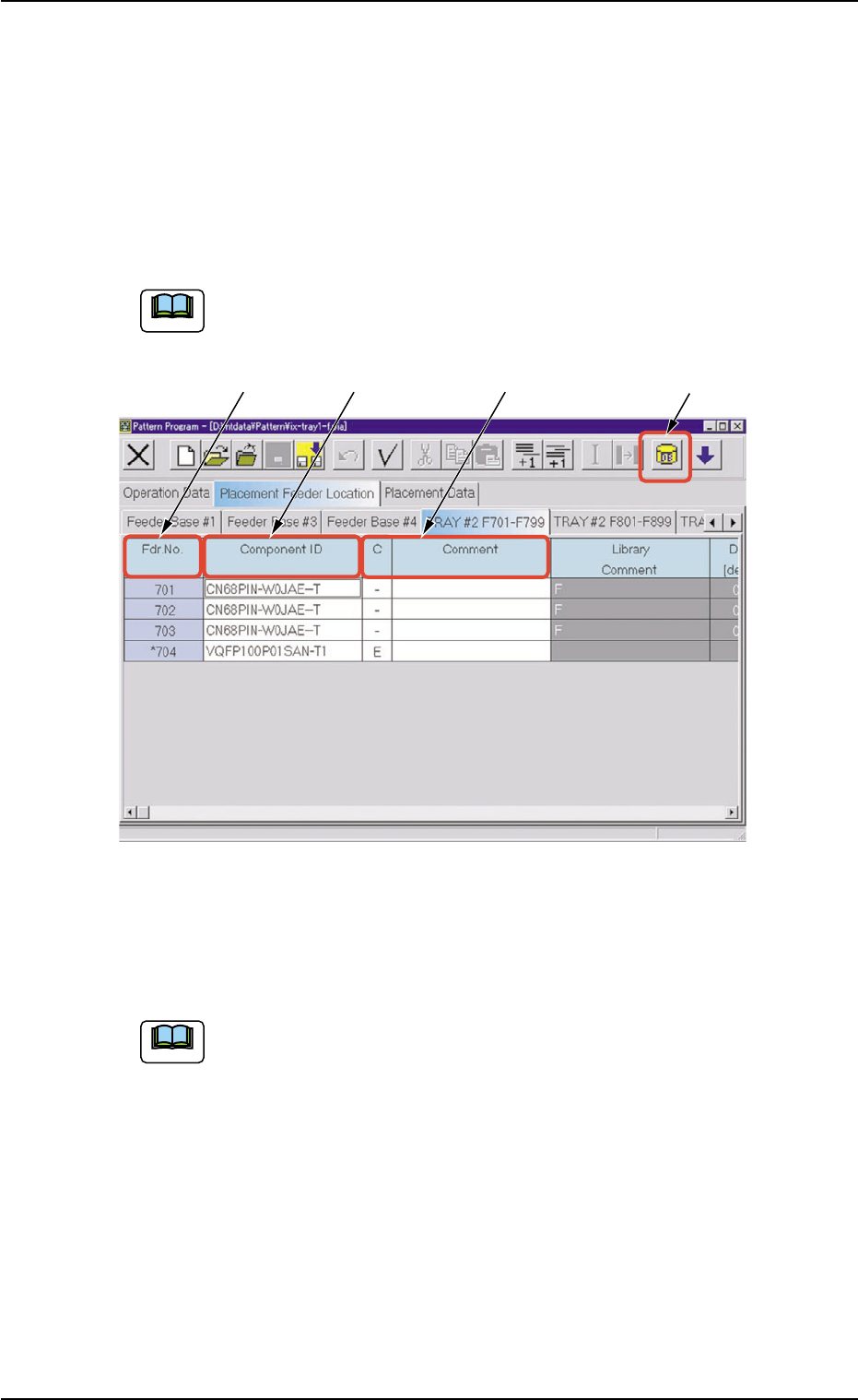
*1 [Component ID List] Icon
When this icon is pressed, the "Component ID List" window opens.
This window enables you to select a component ID from the com-
ponent library and allocate it to an arbitrary feeder (Fdr. No.).
Refer to "4.3.2 "Component ID List" Window" in "Section 2" (the
instruction manual (Vol. 3: Programming and Machine Data) of the
main machine) for details.
1.3 "Placement Feeder Location" Tab
0311-002 3-8 AHI01EGP
*1
*2 *3
*4
Note
Note
*2 Fdr. No.
Shown under this title are the feeder Nos.
Refer to "
••
••
• Operation Procedure" (described later) for the
detailed information on how to add or delete feeder Nos.
(Fdr. Nos.).
*3 Component ID
Displayed are the currently allocated component IDs.
Refer to "4.3.2 "Component ID List" Window" in "Section
2" (the instruction manual (Vol. 3: Programming and Ma-
chine Data) of the main machine) for the detailed informa-
tion on how to enter or delete component IDs.
*4 C, Comment
Enter parameters in these text boxes.
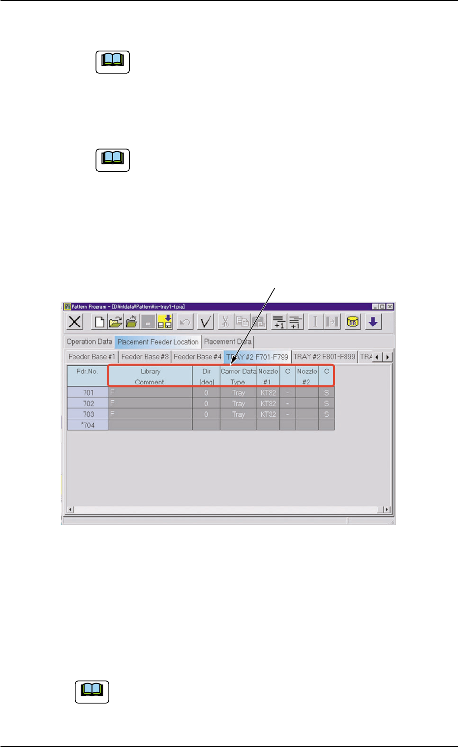
Fig. C11-1 "TRAY #2 F701-F799" Tab Sheet
*5 Library Comment, Dir [deg], Carrier Data Type, Nozzle #1, C,
Nozzle #2, C
Displayed are the parameters specified in the component library.
••
••
• Operation Procedure
Refer to "4.3 "Placement Feeder Location" Tab" in "Section 2"
(the instruction manual (Vol. 3: Programming and Machine Data)
of the main machine) for details.
1.3 "Placement Feeder Location" Tab
0311-002 3-9 AHI01EGP
Note
Note
Note
*5