OM-1078-002.pdf - 第134页
L [mm] (Height) The set parameters are used to correct the variations in the pickup height of the individual blocks of each step. These parameters are reflected on the descending stroke of the head required to pick up a …
3. System Setting
3.1 "Offset Data" Tab
3.1.1 "Tray #2" Tab
••
••
• Sheet Layout
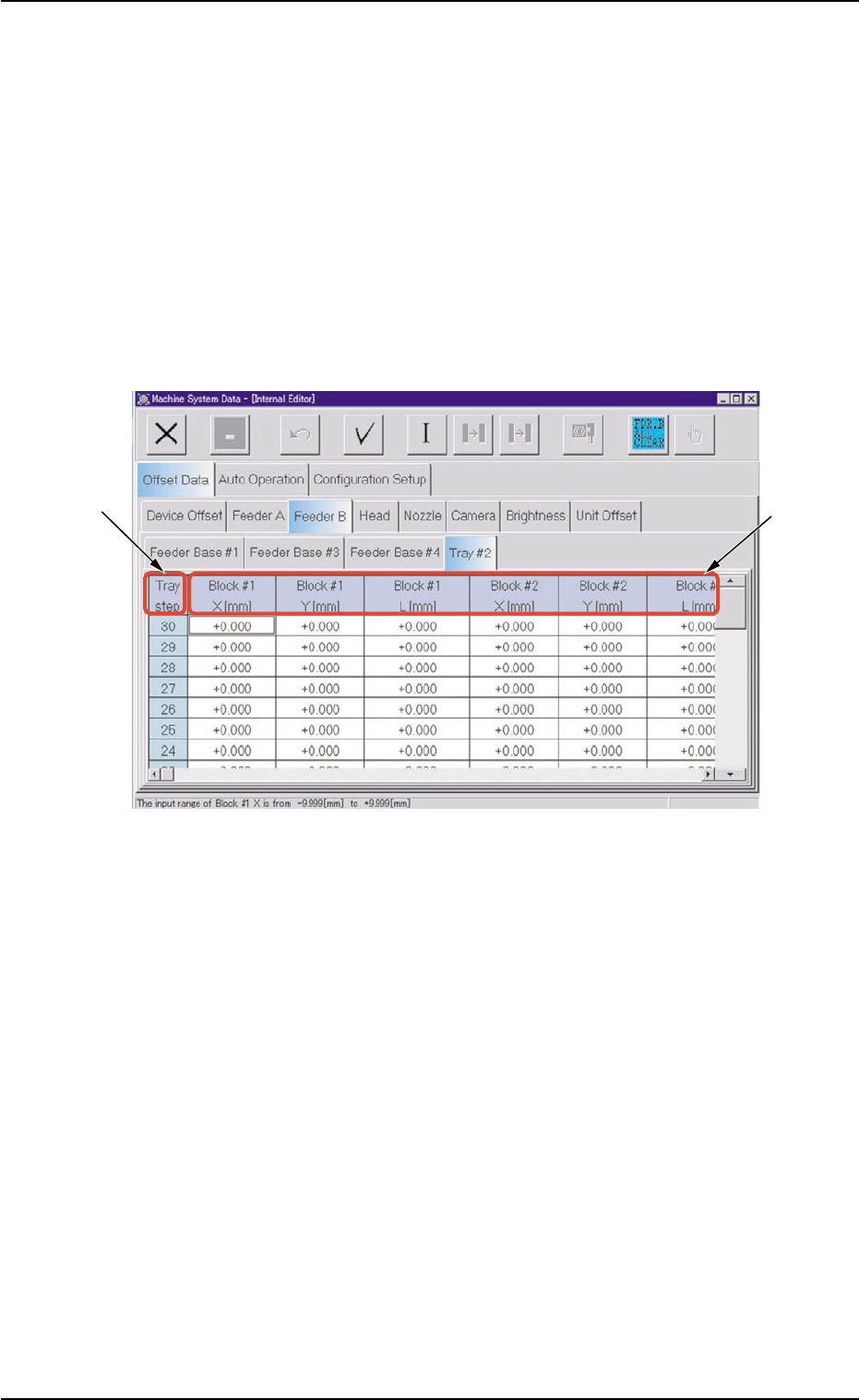
Press the [SYSTEM] button on the main menu bar to open the "Ma-
chine System Data" window.
When the "Feeder B" tab is selected in the "Offset Data" tab sheet
and the "Tray #2" tab is pressed, the following tab sheet appears.
Fig. C15 "Tray #2" Tab Sheet
••
••
• Sheet Composition
*1 Tray step
Displayed are the step Nos.
*2 Block #1 through Block #9
X [mm] (Horizontal), Y [mm] (Vertical)
The set parameters are used to correct the variations in the indi-
vidual blocks of each step.
The values are based on the PL-XY coordinate system must be
entered in these text boxes.
Enter the positional deviations from the pickup position for each in-
dividual pallets, including the traverse drawout position (multi-layer
tray offset), such that components can be picked up at their cen-
ters.
3. System Setting
0311-002 3-13 AHI01EGP
*2
*1

L [mm] (Height)
The set parameters are used to correct the variations in the pickup
height of the individual blocks of each step.
These parameters are reflected on the descending stroke of the
head required to pick up a component.
3.1 "Offset Data" Tab
0109-001 3-14 AHI01EGP
3.1.2 "Tray" Tab
••
••
• Sheet Layout
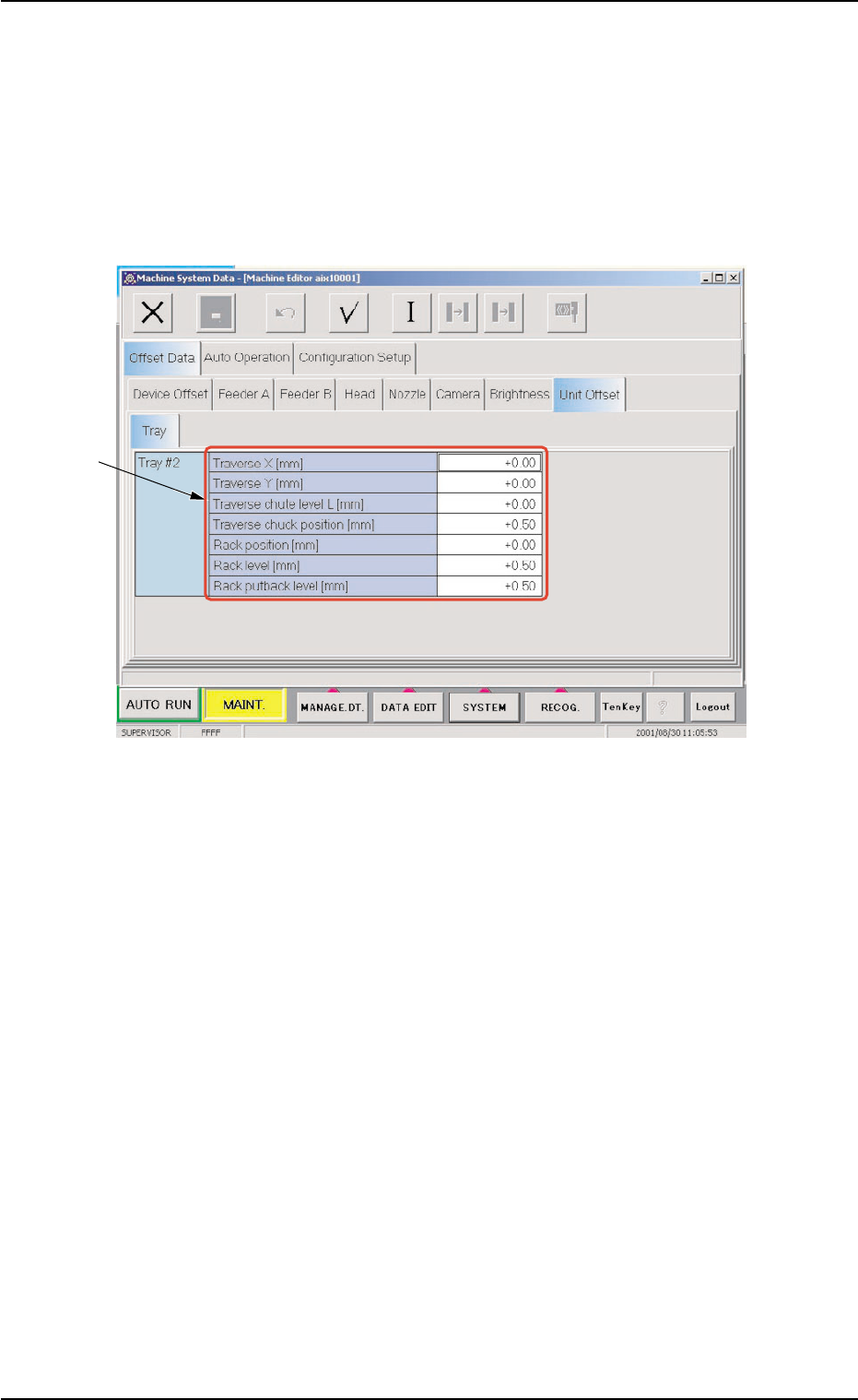
Press the [SYSTEM] button on the main menu bar to open the "Ma-
chine System Data" window.
When the "Unit Offset" tab is selected in the "Offset Data" tab sheet
and the "Tray" tab is pressed, the following tab sheet appears.
Fig. C16 "Tray" Tab Sheet
••
••
• Sheet Composition
*1 Items
The following items are displayed.
Traverse X [mm], Y [mm]
These offset data is used to adjust the position where a pallet is
drawn out from the rack by the traverse shafts. The deviation from
the design position can be set in these text boxes.
X [mm] (Horizontal)
When a pallet is drawn out, the traverse shafts move as far as the
specified distance where the parameter set in this text box is added.
To increase the stroke in the pallet drawing direction, a plus value
must be entered.
0109-001 3-15
AHI01EGP
*1
3.1 "Offset Data" Tab