OM-1078-002.pdf - 第136页
Y [mm] (V ertical) The set value is added to the travel of Beam A when components are picked up from the tray . As the traverse shafts are driven in one direction due to the me- chanical structure, the adjustment of the …
3.1.2 "Tray" Tab
••
••
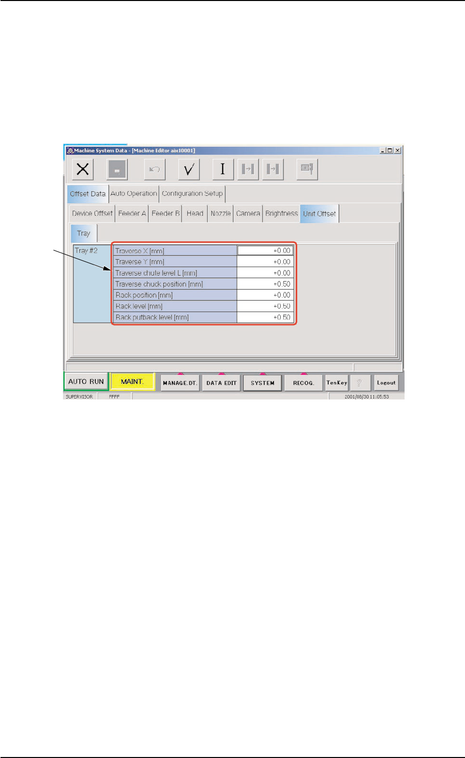
• Sheet Layout
Press the [SYSTEM] button on the main menu bar to open the "Ma-
chine System Data" window.
When the "Unit Offset" tab is selected in the "Offset Data" tab sheet
and the "Tray" tab is pressed, the following tab sheet appears.
Fig. C16 "Tray" Tab Sheet
••
••
• Sheet Composition
*1 Items
The following items are displayed.
Traverse X [mm], Y [mm]
These offset data is used to adjust the position where a pallet is
drawn out from the rack by the traverse shafts. The deviation from
the design position can be set in these text boxes.
X [mm] (Horizontal)
When a pallet is drawn out, the traverse shafts move as far as the
specified distance where the parameter set in this text box is added.
To increase the stroke in the pallet drawing direction, a plus value
must be entered.
0109-001 3-15
AHI01EGP
*1
3.1 "Offset Data" Tab

Y [mm] (Vertical)
The set value is added to the travel of Beam A when components
are picked up from the tray.
As the traverse shafts are driven in one direction due to the me-
chanical structure, the adjustment of the Y direction is performed
using the Y axis of Beam A.
When the actual tray drawing position is located at the lower left
area (viewed from the top), compared with the design position
(P.C.B. Positioning Reference: P0), plus values must be entered in
the "Traverse X [mm]" and "Traverse Y [mm]" text boxes.
Traverse chute level L [mm]
This offset data is used to adjust the level (height) of the pallet draw-
ing chute. The deviation from the design position can be set in this
text box.
When a level lower than the design height is set, a plus value must
be entered in the text box.
The entered plus offset value is added to the travel of the head up/
down shaft required when components are picked up from the tray.
(To increase the downward movement, a plus value must be en-
tered.)
Travers chuck position [mm]
Traverse Axis [mm]
This offset data is used to adjust the chuck position. The deviation
from the design level can be set in this text box.
Rack position [mm]
This offset data is used to adjust the setup position of the rack. The
deviation from the design level can be set in this text box.
The entered offset value is reflected on the travel of the elevator
shaft in the tray unit.
Check how the clutch is engaged when the elevator shaft is moved
to the setup position of the rack according to the design distance
(dimension) and enter an appropriate value in the text box.
To set the elevator position in a higher level, a minus value must be
entered in the text box.
0109-001 3-16
AHI01EGP
3.1 "Offset Data" Tab

Rack level [mm]
This offset data is used to align the traverse chute in height with the
step (shelf) of the rack when a pallet is drawn from the rack. The
deviation from the design level can be set in this text box.
The entered offset value is reflected on the travel of the elevator
shaft in the tray unit when the elevator is moved for the alignment of
the pallet drawing step (pallet drawing from the rack).
To set the elevator position in a higher level, a minus value must be
entered in the text box.
Rack putback level [mm]
This offset data is used to adjust the setup position of the rack. The
deviation from the design level can be set in this text box.
The entered offset value is reflected on the travel of the elevator
shaft in the tray unit.
Check how the engagement is made when the elevator shaft is
moved to the setup position of the rack according to the design dis-
tance (dimension) and enter an appropriate value in the text box.
To set the elevator position in a higher level, a minus value must be
entered in the text box.
3.1 "Offset Data" Tab
0109-001 3-17 AHI01EGP