OM-1078-002.pdf - 第137页
Rack level [mm] This offset data is used to align the traverse chute in height with the step (shelf) of the rack when a pallet is drawn from the rack. The deviation from the design level can be set in this text box. The …

Y [mm] (Vertical)
The set value is added to the travel of Beam A when components
are picked up from the tray.
As the traverse shafts are driven in one direction due to the me-
chanical structure, the adjustment of the Y direction is performed
using the Y axis of Beam A.
When the actual tray drawing position is located at the lower left
area (viewed from the top), compared with the design position
(P.C.B. Positioning Reference: P0), plus values must be entered in
the "Traverse X [mm]" and "Traverse Y [mm]" text boxes.
Traverse chute level L [mm]
This offset data is used to adjust the level (height) of the pallet draw-
ing chute. The deviation from the design position can be set in this
text box.
When a level lower than the design height is set, a plus value must
be entered in the text box.
The entered plus offset value is added to the travel of the head up/
down shaft required when components are picked up from the tray.
(To increase the downward movement, a plus value must be en-
tered.)
Travers chuck position [mm]
Traverse Axis [mm]
This offset data is used to adjust the chuck position. The deviation
from the design level can be set in this text box.
Rack position [mm]
This offset data is used to adjust the setup position of the rack. The
deviation from the design level can be set in this text box.
The entered offset value is reflected on the travel of the elevator
shaft in the tray unit.
Check how the clutch is engaged when the elevator shaft is moved
to the setup position of the rack according to the design distance
(dimension) and enter an appropriate value in the text box.
To set the elevator position in a higher level, a minus value must be
entered in the text box.
0109-001 3-16
AHI01EGP
3.1 "Offset Data" Tab

Rack level [mm]
This offset data is used to align the traverse chute in height with the
step (shelf) of the rack when a pallet is drawn from the rack. The
deviation from the design level can be set in this text box.
The entered offset value is reflected on the travel of the elevator
shaft in the tray unit when the elevator is moved for the alignment of
the pallet drawing step (pallet drawing from the rack).
To set the elevator position in a higher level, a minus value must be
entered in the text box.
Rack putback level [mm]
This offset data is used to adjust the setup position of the rack. The
deviation from the design level can be set in this text box.
The entered offset value is reflected on the travel of the elevator
shaft in the tray unit.
Check how the engagement is made when the elevator shaft is
moved to the setup position of the rack according to the design dis-
tance (dimension) and enter an appropriate value in the text box.
To set the elevator position in a higher level, a minus value must be
entered in the text box.
3.1 "Offset Data" Tab
0109-001 3-17 AHI01EGP
3.2 Auto Operation
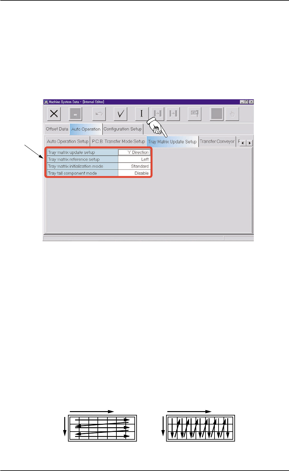
3.2.1 "Tray Matrix Update Setup" Tab
••
••
• Sheet Layout
When the "Tray Matrix Update Setup" tab is pressed in the "Auto Op-
eration" tab sheet, the following tab sheet appears.
Fig. C17 "Tray Matrix Update Setup" Tab Sheet
••
••
• Sheet Composition
*1 Items
The following items are displayed.
Tray matrix update setup
Select "X Direction" or "Y Direction" (direction in which components
should be taken out) in the text box.
In normal cases, "Y Direction" should be selected.
When it is necessary to keep the interchangeability with TIM-X1000/
1100 series, set "X Direction" in the "Tray matrix update setup" text
box.
Fig. C18 Shows the order (arrow directions) in which components are taken out.
3.2 Auto Operation
0311-002 3-18 AHI01EGP
*1
X
YY
X
Selection of "Y Direction"Selection of "X Direction"