OM-1078-002.pdf - 第157页
1.7 Detechment and Attachment of Covers 0204-002 4-15 AHI01EGP 1.7.2 Procedure for Maintenance Cover Attachment (1) While keeping the central maintenance cover in position, tighten two setscrews located inside the safety…
1.7 Detechment and Attachment of Covers
1.7 Detachment and Attachment of Covers
• When the maintenance cover of the multi-layer tray
feeder is detached, the power to the loads is shut
off.
• The multi-layer tray feeder cannot be operated with
the maintenance cover being detached.
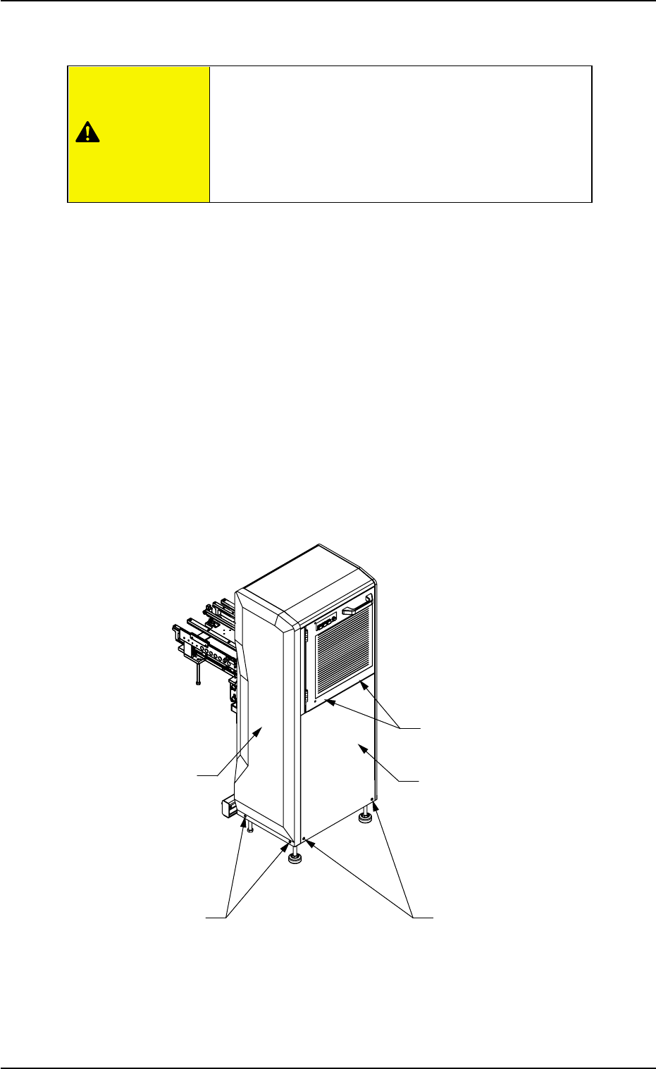
1.7.1 Detachment of Covers
(1) Zero the multi-layer tray feeder.
(2) Manually lower the rack to the position (16th step) for easier lubrica-
tion work.
(3) Shut off the power.
(4) Remove two side setscrews with a cross-head screwdriver.
The side maintenance cover will come off.
(5) Remove two central setscrews with a cross-head screwdriver.
(6) Remove two central setscrews located inside the safety door with a
cross-head screwdriver. The central maintenance cover will come
off.
Fig. D9
0311-003 4-14 AHI01EGP
Side Maintenance Cover
Side Setscrews (2 places)
Central Setscrews (2 places)
(located inside the safety door)
Central Maintenance Cover
Central Setscrews (2 places)
CAUTION

1.7 Detechment and Attachment of Covers
0204-002 4-15 AHI01EGP
1.7.2 Procedure for Maintenance Cover Attachment
(1) While keeping the central maintenance cover in position, tighten two
setscrews located inside the safety door with a cross-head screw-
driver.
(2) Hold the central maintenance cover in position such that the screw
holes of the cover are aligned with those of the multi-layer tray feeder.
(3) Tighten two central setscrews with a cross-head screwdriver while
keeping the central maintenance cover in position.
(4) Hold the side maintenance cover in position such that the screw
holes of the cover are aligned with those of the multi-layer tray feeder.
(5) Tighten two side setscrews with a cross-head screwdriver while
keeping the side maintenance cover in position.
1.8 Lists of Consumables and Important Servicing
Parts
Listed below are the parts that may be consumed within 1 year.
Contact our marketing department or sales agency whenever you
need to purchase some of these parts.
(a) The values in the "Recommended Q’ty/Year" column are
for your reference.
(b) Refer to "1. Periodic Maintenance" in "Section 4" for the
replacement procedures of these parts.
(1) Mechanical Parts for Elevator
Table D5-1
Product Name Part No. Part Name
Standard/
Q’ty
Remarks
Material
AC Servomotor 630 096 0778 MOTOR, SGMAH-04 1 - ER-2 002
AC-SERVO AAA2B
(2) Electrical Parts for Elevator
Table D5-2
Product Name Part No. Part Name
Standard/
Q’ty
Remarks
Material
Capacitor 630 089 2079 SENSOR, EX-23 1 - ER-7 037
PELEC
Capacitor 630 089 2086 SENSOR, OS-EX20E- 1 - ER-7 038
PELEC (SLIT) 05X3
Photosensor 630 000 0252 SENSOR, EE-SX671 4 - ER-7 046
PHOTO
1.8 Lists of Consumables and Important Servicing Parts
0311-002 4-15-1 AHI01EGP
Recom-
mended
Q’ty/Year
Exploded
View No.
(Reference)
Recom-
mended
Q’ty/Year
Exploded
View No.
(Reference)
Note