OM-1078-002.pdf - 第162页
2.2.3 [EMERGENCY STOP] Button ON (Pressed) T able D8 Symptom (1 ) The [POWER ON] turns red and the following window appears. Fig. D9-1 Cause (1) An [EMERGENCY STOP] button was pressed. Remedy (1) Check the displayed cont…
2.2 Easy Troubleshooting
This session describes the countermeasures against easy problems
to be taken by the operator of the machine.
When the operator cannot solve a problem, he/she should get in
contact with the supervisor (a person in charge of machine manage-
ment).
2.2.1 Impossible Power Operation of Multi-Layer Tray Feeder
Table D6
Symptom The elevator axis cannot be powered.
Cause (Cause 1) The main machine is not powered.
(Cause 2) The connector is disconnected.
(Cause 3) The safety door is not closed.
Remedy (Remedy 1) Power the main machine.
Refer to "2.1 Power Operation Impossible" in "Section 2" (the
instruction manual (Vol. 4: Maintenance and Troubleshooting) of
the main machine) for details.
(Remedy 2) Confirm that the connector is connected.
(Remedy 3) Close the safety door.
2.2.2 Countermeasures against Pick-Up Errors
Table D7
Symptom The component pick-up rate has deteriorated.
Cause (Cause 1) The vacuum pressure for component picks is not proper.
(Cause 2) The vacuum nozzle is not proper.
(Cause 3) The component pick-up position is not normal.
(Cause 4) There is a problem in transition of the pallet.
(Cause 5) The tray is not fixed normally.
(Cause 6) The pallet is warped.
(Cause 7) The anti-warpage plate for the pallet on the traverses is worn out.
Remedy (Remedy 1) Check the vacuum pumps and tubes.
(Remedy 2) Use a proper vacuum nozzle for the component.
(Remedy 3) Confirm that correct parameters are set as offsets for the
traverse axis, tray offsets in the pallet, tray matrix dimensions,
and the height data for tray components.
(Remedy 4) Check the elevator offset.
(Remedy 5) Fix the tray normally.
(Remedy 6) Check the flatness of the pallet and how the rails on both sides
are worn out.
(Remedy 7) Place the pallet on the chute and check the clearance.
2.2 Easy Troubleshooting
0311-003 4-17 AHI01EGP
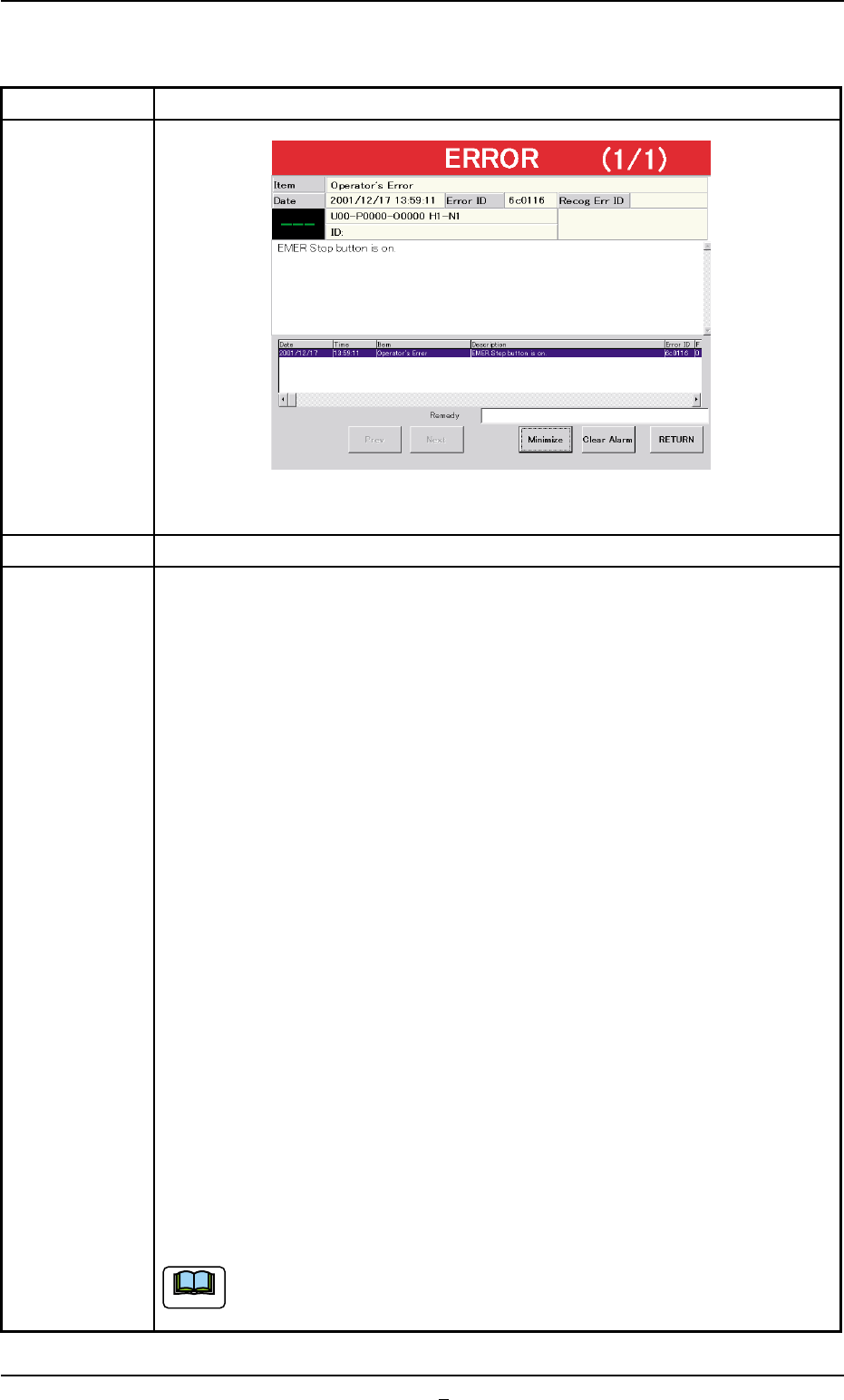
2.2.3 [EMERGENCY STOP] Button ON (Pressed)
Table D8
Symptom (1) The [POWER ON] turns red and the following window appears.
Fig. D9-1
Cause (1) An [EMERGENCY STOP] button was pressed.
Remedy (1) Check the displayed contents.
(2) Press the [RETURN] button.
(3) Remove the cause of the problem that prompted the operator to press
the [EMERGENCY STOP] button.
(4) Check the multi-layer tray feeder.
When the component to be picked up is left in the supply position, re-
move it.
(5) Check if there is a component which has dropped inside the machine.
(6) Check whether or not the P.C.B. in the middle of component placement
is located correctly (not out of the P.C.B. positioning section) and the
components are placed normally (not dispersed).
(7) Turn the [EMERGENCY STOP] button clockwise to release the locked
condition.
(8) Hold down the [POWER ON] button for more than 1 second to re-supply
power to the machine.
• When the LED of the [POWER ON] button illuminates in yellowish
green, it indicates that the power is supplied to the machine.
When the LED is kept red, re-check the cause and remove it.
(9) Press the [Up/Down Axis] button in the "Head #1" or the "Head #2" group
box of the "Manual Axis Opn." tab sheet. (Operation Sequence: [MAINT.]
Button Æ [MNL OPN.] Button Æ "Manual Axis Opn." Tab Sheet) After
that, press the [Tray2 Axis] button in the "Zeroing Opn." tab sheet for the
zeroing operation.
When the pallet is located on the traverses or in the middle of being
drawn out, it is stored in the elevator.
2.2 Easy Troubleshooting
0311-002 4-17-1 AHI01EGP
Note
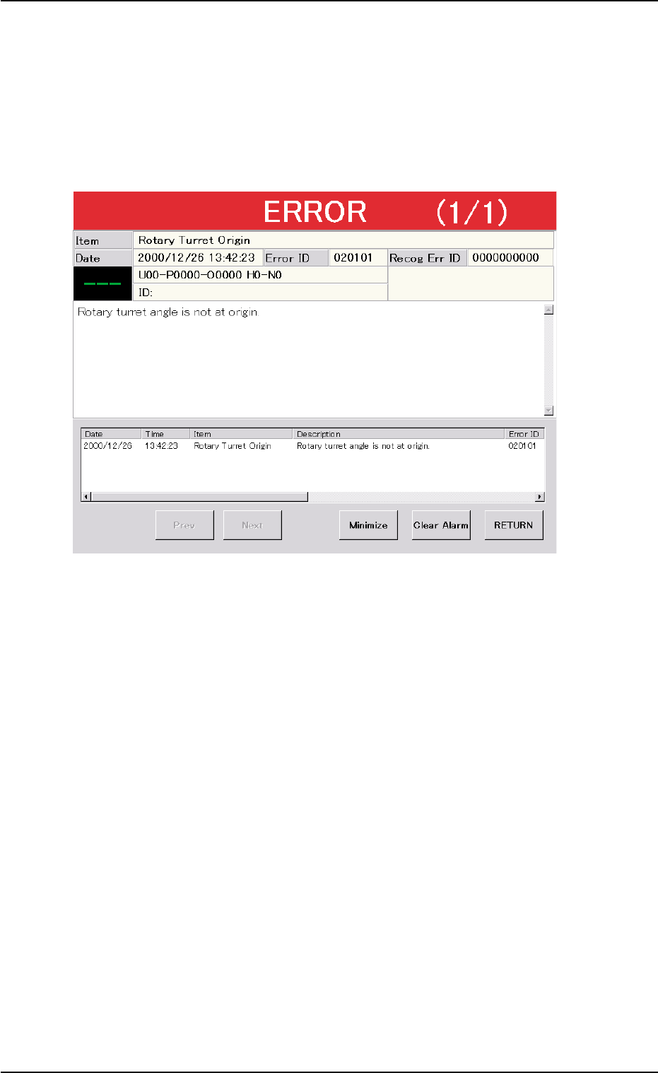
2.3 Troubleshooting after "ERROR" Window
(Error ID)
Refer to "3. Troubleshooting after "ERROR" Window (Error ID)" in
"Section 2" (the instruction manual (Vol. 4: Maintenance and Trouble-
shooting) of the main machine) for details.
Fig. D10 Example of "ERROR" Window
2.3.1 Typical Description
Refer to "3.1 Typical Description" in "Section 2" (the instruction
manual (Vol. 4: Maintenance and Troubleshooting) of the main ma-
chine) for details.
2.3.2 Error IDs and Controlled Areas
Refer to "3.2 Error IDs and Controlled Areas" in "Section 2" (the in-
struction manual (Vol. 4: Maintenance and Troubleshooting) of the
main machine) for details.
2.3 Troubleshooting after "ERROR" Window (Error ID)
0311-002 4-18 AHI01EGP