OM-1078-002.pdf - 第203页
AHI01EGP 0109-001 5-2

AHI01EGP
Section 5
Pneumatic and Electrical Diagrams
This section describes the pneumatic diagram, the parts
location, the location of sensors and loads, the electrical
circuit diagrams, etc.
As this section contains highly sophisticated contents, it
should carefully be referred to.
0311-002 5-1

AHI01EGP
0109-001 5-2
AHI01EGP
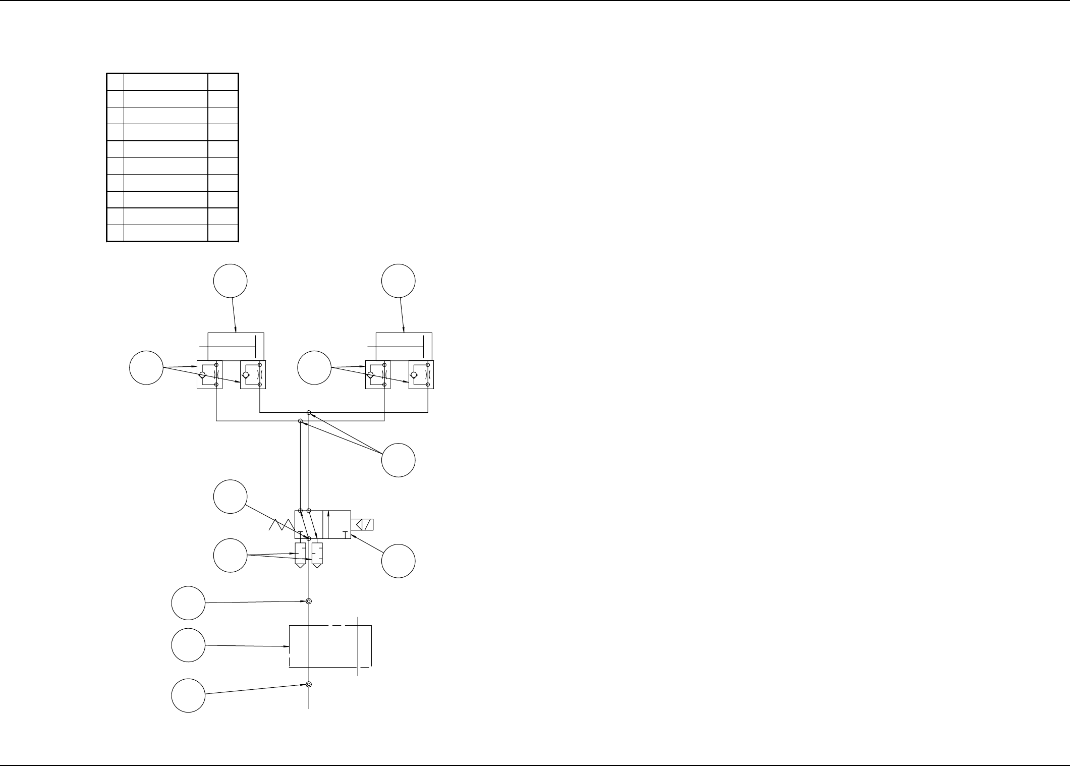
1. Pneumatic Diagram
0109-001-(M756XER--0002) 5-3
7
82
9
1
2
3
4
No.
5
2
4
1
2
170 mm/sec
1
1
2
8
1
1
1
φ8
1
5
φ8
(From the main machine)
9
7
φ6 φ6
2
4
3
φ6
6
6
Half Union
Straight Joint
170 mm/sec
Name
Q'ty
Cylinder
Speed Controller
Solenoid Valve
Bonding Tube
Silencer
Straight Joint for
Different Diameters
Cheese
1. Pneumatic Diagram