OM-1078-002.pdf - 第212页
4. Electrical Circuit Diagram 0109-001 5-1 1 AH101EGP
4. Electrical Circuit Diagram
0109-001 5-10 AHI01EGP
4. Electrical Circuit Diagram
0109-001 5-11 AH101EGP
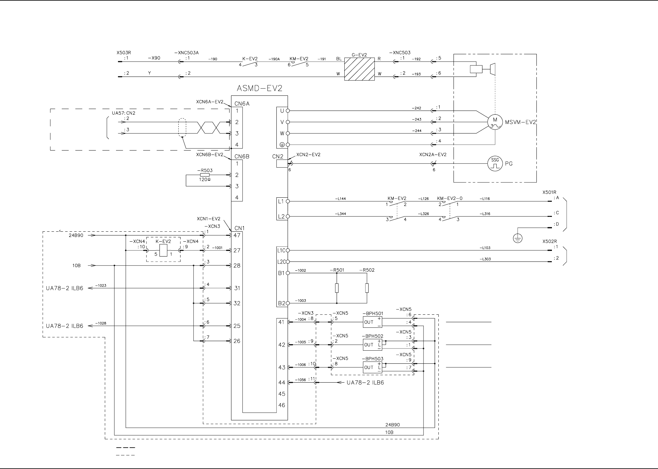
AHI01EGP
Notes: (a) Surrounded by
100 V AC
(For Brake)
Note (a)
From Main
Machine EB005
Mechatrolink
Shielded
Terminal
Resistance
Note (b)
Brake
Power Supply for Brake
(broken line) are the wires connected to the main machine.
(b) Surrounded by
(broken line) is the wiring in the relay board.
To XCN8LB6: A1
To XCN8LB6: A6
Shell
200 V AC
Control Circuit Power Supply
Brake
Elevator Axis
Encoder
200 V AC
Main Circuit Power Supply
Regenerative Resistance
Elevator Axis Origin
Elevator Axis Limit (+)
Elevator Axis Limit (-)
From XCN8LB6: B2
0311-002 C(M756WEV--2101) 5-12
4.2 Electric Circuit Diagram for Each Section
4.2 Electrical Circuit Diagram for Each Section
Tray 30 Steps Elevator Circuit Diagram