OM-1078-002.pdf - 第215页
AHI01EGP EV -Axis Servo Alarm Main Machine Emergency Stop Input for Main Machine Interface Open Maintenance Cover Detection Note (e) Load Power Shut-Off Detection (Supply Check) EV -Axis Positioning Completed ALL CHANGE …
AHI01EGP
-1152-1151
-1012
10B 24B90
-1022A
-1025
-1058
6K
10K
24B90
10B
24B91
-1013-1011-1010
-1009-1008
-1022 -1021
-1017
-1018
-1016
-1014
-1015
-1020
-1019
-HD008
43
-K509
6W 470 Ω
-K509
-R009
18
-R008
-V008
:2:1
-XCN13 -XCN14
:1 :2
-SQ503 -SQ504
-V003
-R003 -HD003
-HD001-R001
-V001
-XCN4
-XCN4
-XCN4
-XCN4
-XCN4
-XCN4
-XCN1
-V002
-R002 -HD002
JP
-XCN2:2
-XCN2:1
X504R -XCN1
OUTIN
0V0V
:8
:7
-XCN1
24B90
10B
:1
:2
X505R
-XCN5
:22:23
-XCN5
-XCN4
:15 :16
-XCN4
-XCN4
:14:13
-XCN4
:8
:7
:4
-XCN4
:2
-XCN6-XCN6
:1
-XCN7
:2:1
-XCN7
-XCN12
:2
:1
-XCN12
:6
:5
:3
-XCN4
:12 :11
-XCN4
:2
:1
-XCN4
-XCN6-XCN6
-XCN7-XCN7
-XCN7 -XCN7
-XCN6-XCN6
:6:5
:6:5
:4:3
:4:3
:3
:1
:2
:6
:5
:4
KM-
-YSOL501
-YSOL502
-HD501
-K502
43
-K505
4311 12
-SQ501
11 12
-SQ502
16
-K504
-SQ502
424141 42
-SQ501
81
-K502
X504R
E2E1
-K508
43
34
:5
:6
:8
:7
34
-K507
E1 E2
16
-K503
:2
24A4
-K506
KM-EV2
A1 A2
A2A1
EV2-0
24A8
:4
3433
23 24
-K501
K1 K2
1413
K2
K1
4241
K2
K1
K2
K1
K2
K1
D
X2
22 21
KM-EV2-0KM-EV2
2221
X1
C
:1
X504R
:3
24A7
10A
+5V+24V
Lower Safety
Door
From the
main machine
For I/O from the
main machine
From the
main machine
Upper Safety
Door Lock
Lower Safety
Door Lock
Note (a)
Upper Safety
Door
Load Power
Supply
Open Maintenance
Cover Detection
Safety Door Electromagnetic
Lock Check Upper/Lower
To UA78 ILB4 CN4: A15
From UA78 ILB4 CN4: B8
From UA78-2 ILB6 XCN8LB6: B4
To UA78-2 ILB6 XCN8LB6: A3
DC Converter
Maintenance
Cover #1
Note (a)
Notes: (a) Short-Circuited, excluding the time when the machine is equipped with the option for the magazine.
(b) Not connected, excluding the time when the machine is equipped with the option for the magazine.
(c) Surrounded by (broken line) is the wiring in the relay board.
Maintenance
Cover #2
Note (b)
EV-Axis Driving Power
Supply Shut-Off
Main Machine Emergency Stop
Power
Lamp
Lower Safety Door
Electromagnetic Lock
Upper Safety Door
Electromagnetic Lock
Load Power
Shut-Off Detection
(Supply Check)
(-SQ501)
(-SQ502)
Note (C)
0311-002 C(M756WEV--2102) 5-13
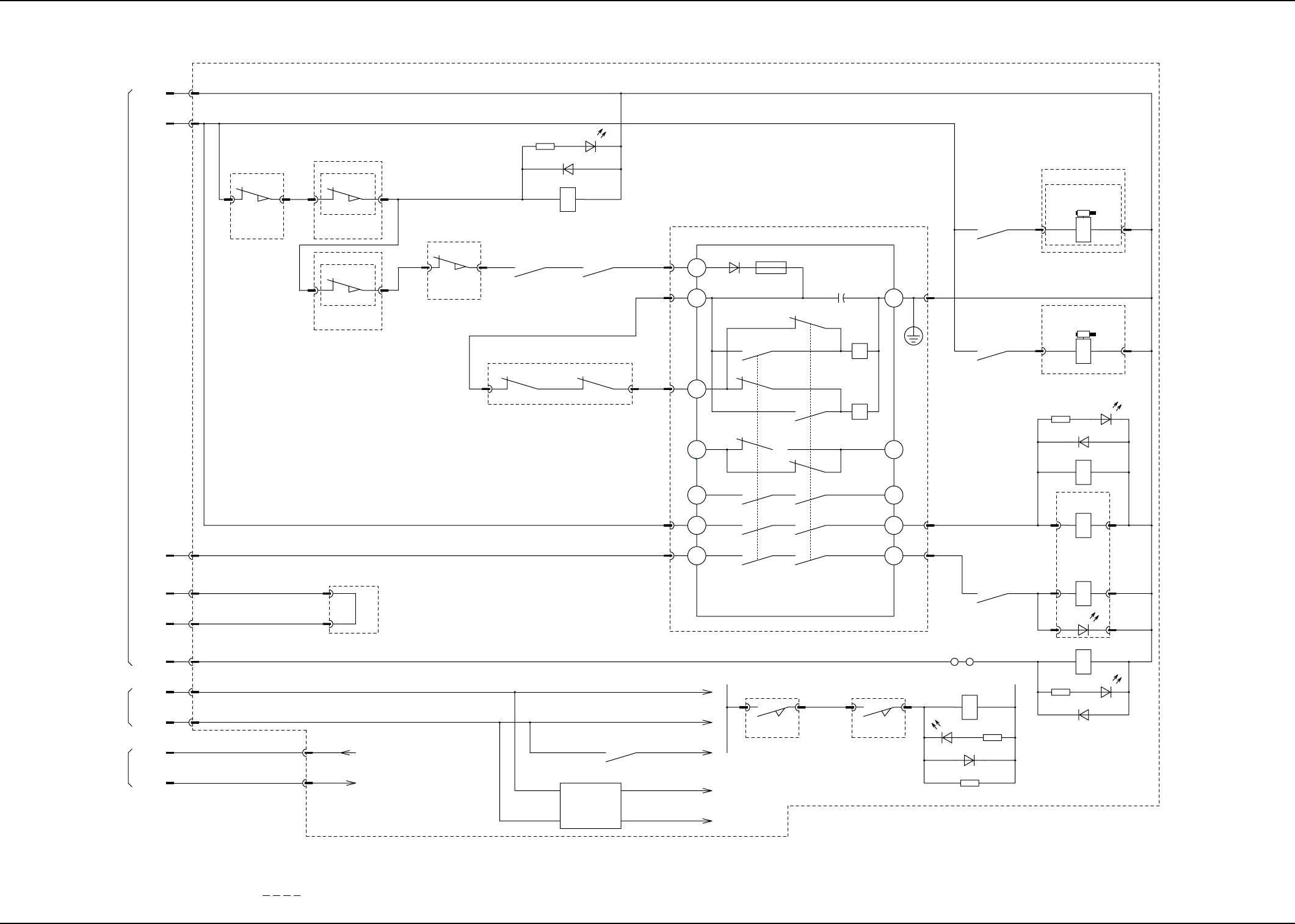
Tray 30 Steps Power Circuit Diagram
4.2 Electric Circuit Diagram for Each Section
AHI01EGP
EV-Axis Servo Alarm
Main Machine Emergency Stop
Input for Main
Machine Interface
Open Maintenance
Cover Detection
Note (e)
Load Power
Shut-Off Detection
(Supply Check)
EV-Axis Positioning
Completed
ALL CHANGE PB
Upper Safety Door
Check
Lower Safety Door
Check
Safety Door
Electromagnetic Lock
Check Upper/Lower
READY PB
HOME POSITION PB
Type Code (1)
Type Code (2)
Type Code (3)
Not Available
Note (f)
From the cable on
the main machine
side
Shielded
Note (a)
From ASMD-EV2:CN1:25
I/O Board ILB6
From ASMD-EV2:CN1:31
From XCN2:2
Note (c)
Note (b)
Note (d)
Ejected Pallet
Detection
(Traverse Side)
Closed Rack Shutter
(Operator Side) Check
Open Right Rack Shutter
(Traverse Side) Check
Open Left Rack Shutter
(Traverse Side) Check
Closed Left Rack Shutter
(Traverse Side) Check
Reserved Input 1
Closed Right Rack Shutter
(Traverse Side) Check
Not Available
Not Available
Not Available
Not Available
Not Available
Not Available
Not Available
Not Available
Not Available
Note (e)
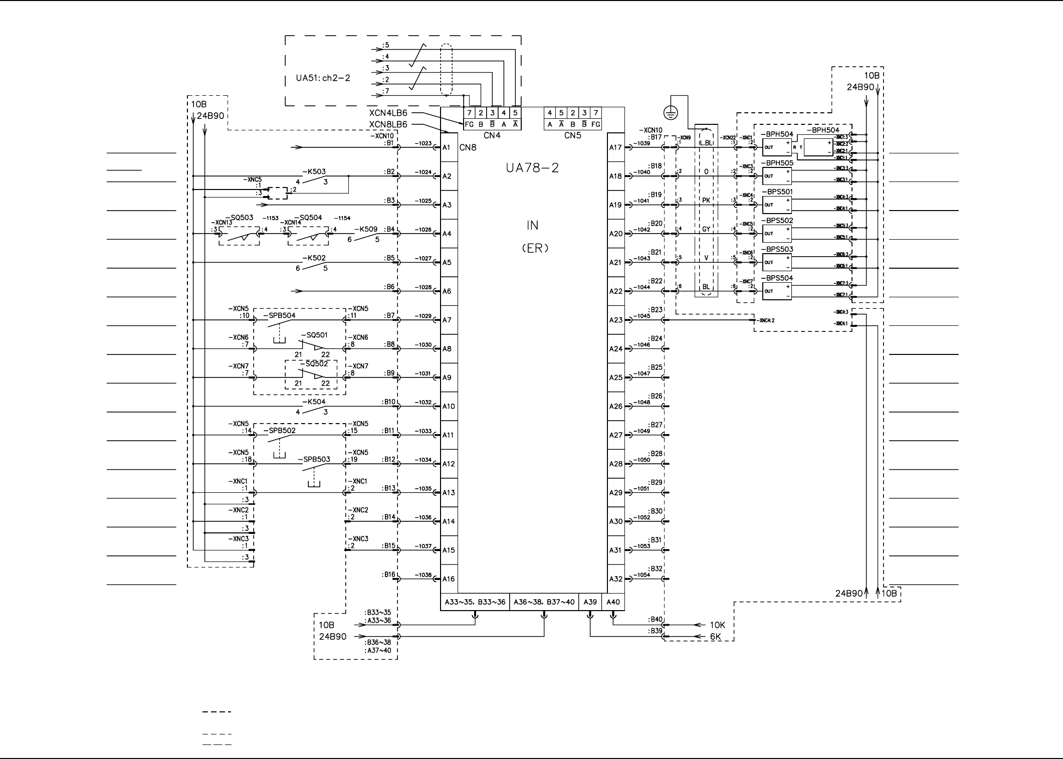
Notes: (a) Connect the drain line to Terminal No. 7 of the connector.
(b) Connection of Bonding Flat Cable (19 cores) (External 6 Colors Used)
(c) Not Connected, excluding the time when the machine is
equipped with the option for the magazine.
(d) Surrounded by (broken line) is the wiring in
the replenishment SW board.
(e) Surrounded by (broken line) is the wiring in the relay board.
(f) Surrounded by (broken line) are the wires connected to the main machine.
0311-002 B(M756WEV--2103) 5-14
I/O Board ILB6 (1/2)
4.2 Electric Circuit Diagram for Each Section

AHI01EGP
Load Power Supply
Note (c)
EV-Axis Speed
Reduction Stop
EV-Axis Driving
Power Supply Shut-Off
Output for Main
Machine Interface
ALL CHANGE PB LED
Reserved Output 1
Reserved Output 2
Reserved Output 3
Rack Shutter
(Traverse Side) Open
Reserved Output 4
(Not Available)
Upper Safety Door
Electromagnetic Lock
Lower Safety Door
Electromagnetic Lock
Reserved Output 5
Reserved Output 6
Reserved Output 7
Reserved Output 8
To -XCN2:1
To ASMD-EV2:CN01:44
I/O Board ILB6
Note (a)
Shielded
To UA76-4 IO16:CN3
Notes: (a) Connection of Bonding Flat Cable (19 cores) (Internal 1 Color Used)
(b) Connection of Bonding Flat Cable (19 cores) (External 2 Colors Used)
(c) Surrounded by (broken line) is the wiring in the relay board.
(d) Surrounded by (broken line) is the wiring in the replenishment SW board.
Note (b)Note (d)
0311-002 B(M756WEV--2104) 5-15
I/O Board ILB6 (2/2)
4.2 Electric Circuit Diagram for Each Section