OM-1078-002.pdf - 第219页
AHI01EGP T raverse Shaft Limit (+) Note: (a) Surrounded by (broken line) are the wires connected to the main machine. Note (a) Motor Relay Board Fourth Axis Motor Controller 2 I/O Relay Board T raverse Shaft Servomotor E…
AHI01EGP
From UA78-2ILB6:CN7
Note (d)
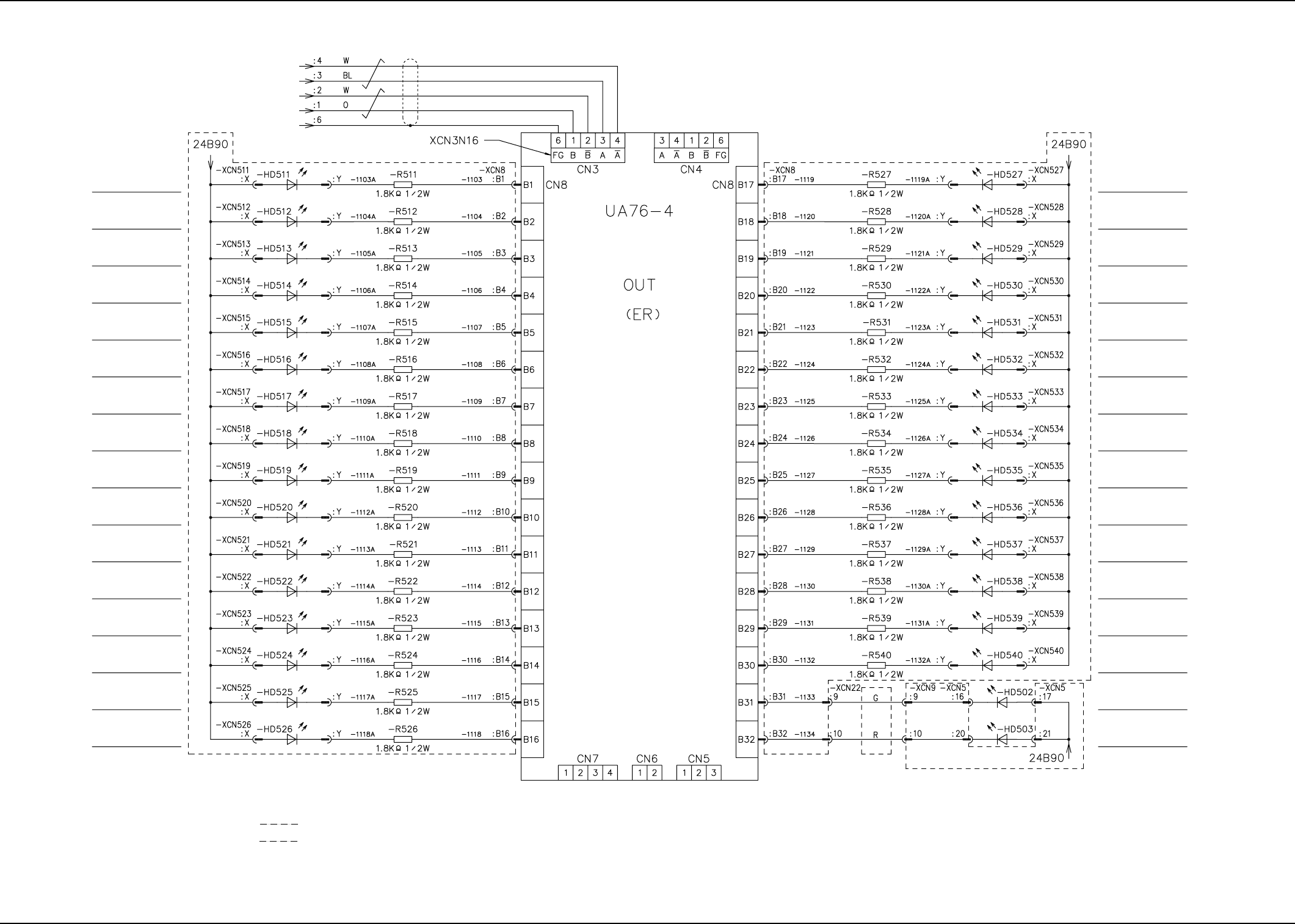
Empty Tray Indicating
LED Step 1
Empty Tray Indicating
LED Step 2
Empty Tray Indicating
LED Step 3
Empty Tray Indicating
LED Step 4
Empty Tray Indicating
LED Step 5
Empty Tray Indicating
LED Step 6
Empty Tray Indicating
LED Step 7
Empty Tray Indicating
LED Step 8
Empty Tray Indicating
LED Step 9
Empty Tray Indicating
LED Step 10
Empty Tray Indicating
LED Step 11
Empty Tray Indicating
LED Step 12
Empty Tray Indicating
LED Step 13
Empty Tray Indicating
LED Step 14
Empty Tray Indicating
LED Step 15
Empty Tray Indicating
LED Step 16
Note (b)
Note (e)
Shielded
Note (d)
Empty Tray Indicating
LED Step 17
Empty Tray Indicating
LED Step 18
Empty Tray Indicating
LED Step 19
Empty Tray Indicating
LED Step 20
Empty Tray Indicating
LED Step 21
Empty Tray Indicating
LED Step 22
Empty Tray Indicating
LED Step 23
Empty Tray Indicating
LED Step 24
Empty Tray Indicating
LED Step 25
Empty Tray Indicating
LED Step 26
Empty Tray Indicating
LED Step 27
Empty Tray Indicating
LED Step 28
Empty Tray Indicating
LED Step 29
Empty Tray Indicating
LED Step 30
READY PB LED
HOME POSITION
PB LED
Note (c)
Note (a)
Notes: (a) Connection of Bonding Flat Cable (19 cores) (External 2 Colors Used)
(b) Connection of Bonding Flat Cable (2 pairs)
(c) Surrounded by (broken line) is the wiring in the relay board.
(d) Surrounded by (broken line) is the wiring in the replenishment SW board.
(e) Attach this such that Type Indication 19-159.035 of replenishment switches -HD511
(-SPB511) through -HD540 (-SPB540) becomes visible from the upper surface
(components mounted) of the P.C.B. (viewed from the top).
I/O Board IO16
0311-002 B(M756WEV--2106) 5-17
I/O Board IO16 (2/2)
4.2 Electric Circuit Diagram for Each Section
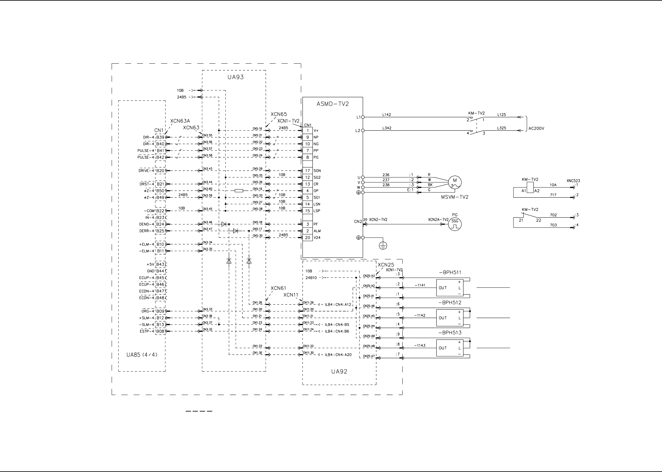
AHI01EGP
Traverse Shaft
Limit (+)
Note: (a) Surrounded by (broken line) are the wires connected to the main machine.
Note (a)
Motor Relay Board
Fourth Axis
Motor Controller 2
I/O Relay Board
Traverse Shaft Servomotor
Encoder
Main Circuit
Power Supply
Traverse Shaft
Origin
Traverse Shaft
Limit (-)
0109-001C(M756WTV--2101) 5-18
Tray 30 Steps TV2 Axis Motor Circuit Diagram
4.2 Electric Circuit Diagram for Each Section
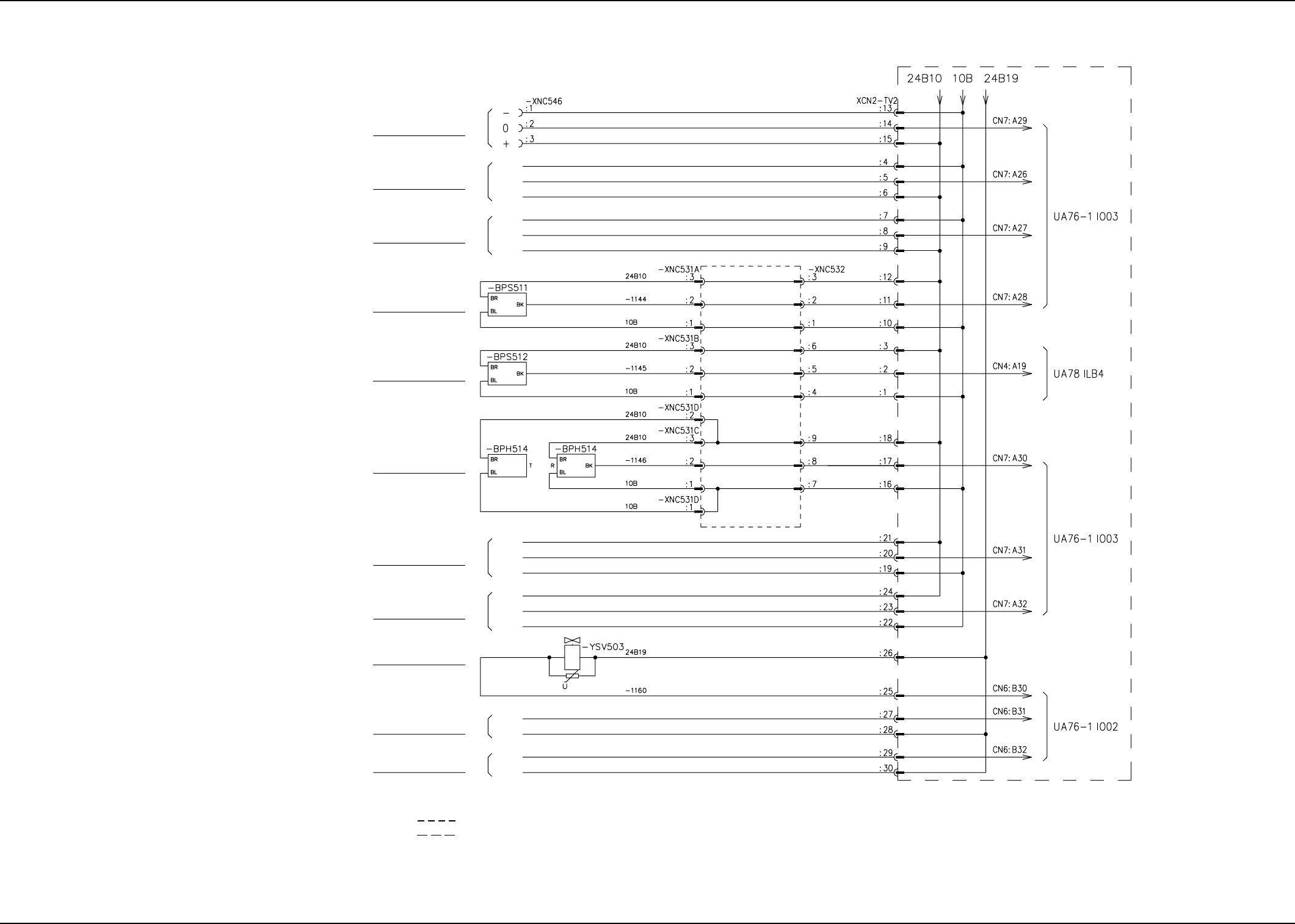
AHI01EGP
Lower Transfer Level Check
(Reserved Input)
Reserved Input
Upper Transfer Level Check
(Reserved Input)
Reserved Input
Reserved Input
Open Pallet Chuck
Claw Check
Closed Pallet Chuck
Claw Check
Pallet Chuck Claw
Connection Check
Pallet Chuck Claw Open
Transfer Rail Upward
Movement
(Reserved Output)
Transfer Rail Downward
Movement
(Reserved Output)
Note (c)
Note (c)
Note (d)
Note (d)
Note (c)
Note (c)
Note (a)
Note (b)
Note: (a) Surrounded by (broken line) are the cable bearers.
(b) Surrounded by (broken line) are the wires connected to the main machine.
(c) Mass Insulation of Pin Nos. 4, 7, 19, 22, Mass Insulation of Pin Nos. 5, 8, 20, and 23, Mass Insulation of Pin Nos. 6, 9, 21, and 24
(d) Mass Insulation of Pin Nos. 27 and 29 and Mass Insulation of Pin Nos. 28 and 30
0311-002B(M756WTV--2102) 5-19
Tray 30 Steps Traverse Connection Diagram (1)
4.2 Electric Circuit Diagram for Each Section