OM-1078-002.pdf - 第220页
AHI01EGP Lower T ransfer Level Check (Reserved Input) Reserved Input Upper T ransfer Level Check (Reserved Input) Reserved Input Reserved Input Open Pallet Chuck Claw Check Closed Pallet Chuck Claw Check Pallet Chuck Cla…
AHI01EGP
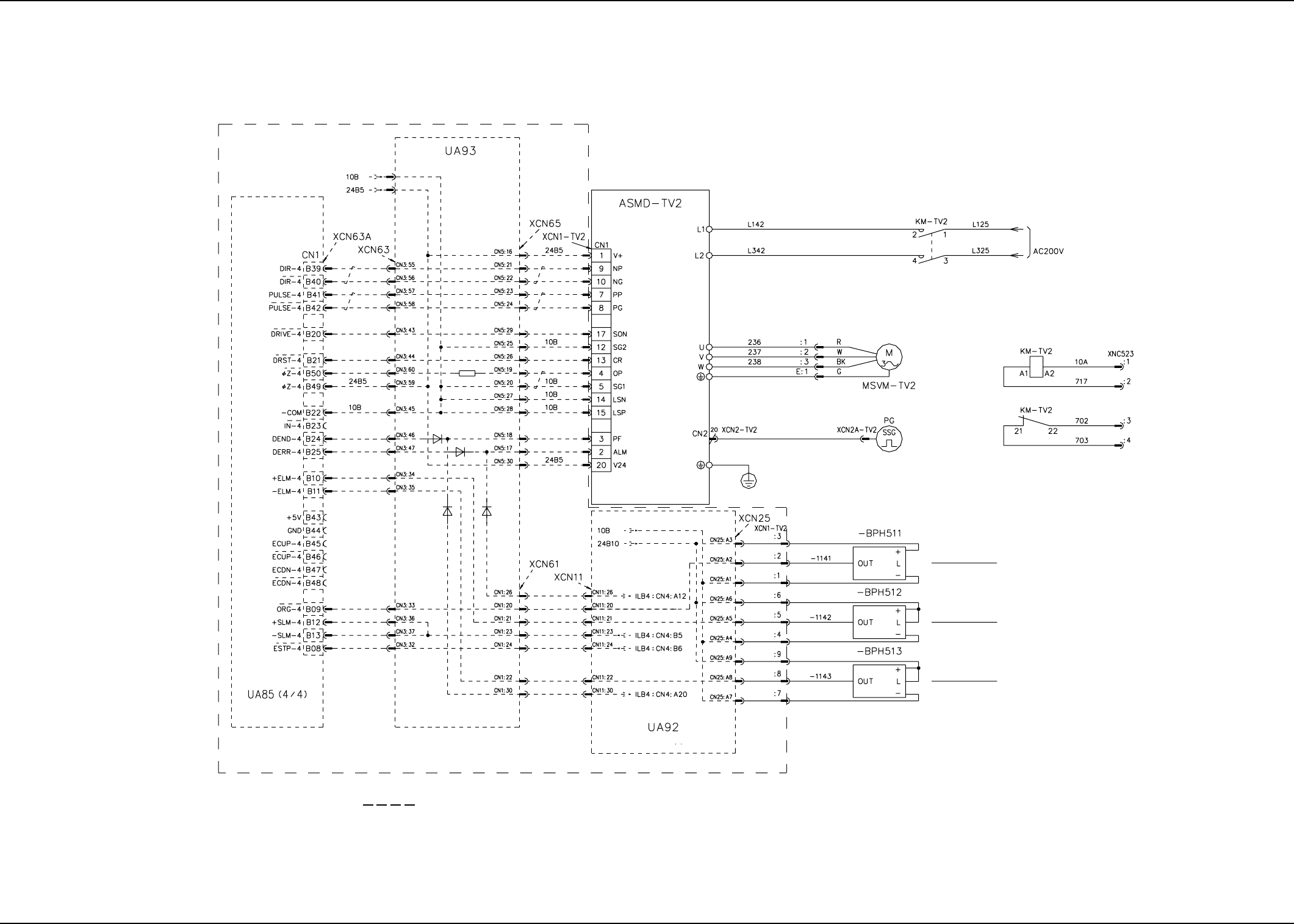
Traverse Shaft
Limit (+)
Note: (a) Surrounded by (broken line) are the wires connected to the main machine.
Note (a)
Motor Relay Board
Fourth Axis
Motor Controller 2
I/O Relay Board
Traverse Shaft Servomotor
Encoder
Main Circuit
Power Supply
Traverse Shaft
Origin
Traverse Shaft
Limit (-)
0109-001C(M756WTV--2101) 5-18
Tray 30 Steps TV2 Axis Motor Circuit Diagram
4.2 Electric Circuit Diagram for Each Section
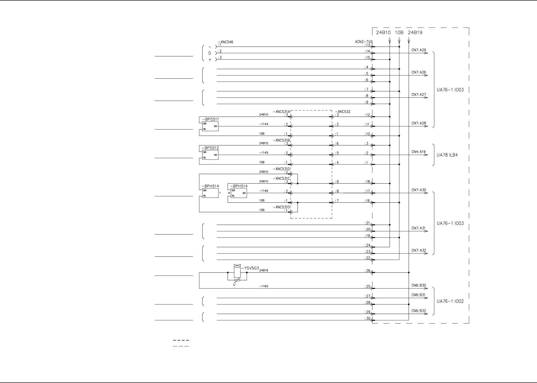
AHI01EGP
Lower Transfer Level Check
(Reserved Input)
Reserved Input
Upper Transfer Level Check
(Reserved Input)
Reserved Input
Reserved Input
Open Pallet Chuck
Claw Check
Closed Pallet Chuck
Claw Check
Pallet Chuck Claw
Connection Check
Pallet Chuck Claw Open
Transfer Rail Upward
Movement
(Reserved Output)
Transfer Rail Downward
Movement
(Reserved Output)
Note (c)
Note (c)
Note (d)
Note (d)
Note (c)
Note (c)
Note (a)
Note (b)
Note: (a) Surrounded by (broken line) are the cable bearers.
(b) Surrounded by (broken line) are the wires connected to the main machine.
(c) Mass Insulation of Pin Nos. 4, 7, 19, 22, Mass Insulation of Pin Nos. 5, 8, 20, and 23, Mass Insulation of Pin Nos. 6, 9, 21, and 24
(d) Mass Insulation of Pin Nos. 27 and 29 and Mass Insulation of Pin Nos. 28 and 30
0311-002B(M756WTV--2102) 5-19
Tray 30 Steps Traverse Connection Diagram (1)
4.2 Electric Circuit Diagram for Each Section
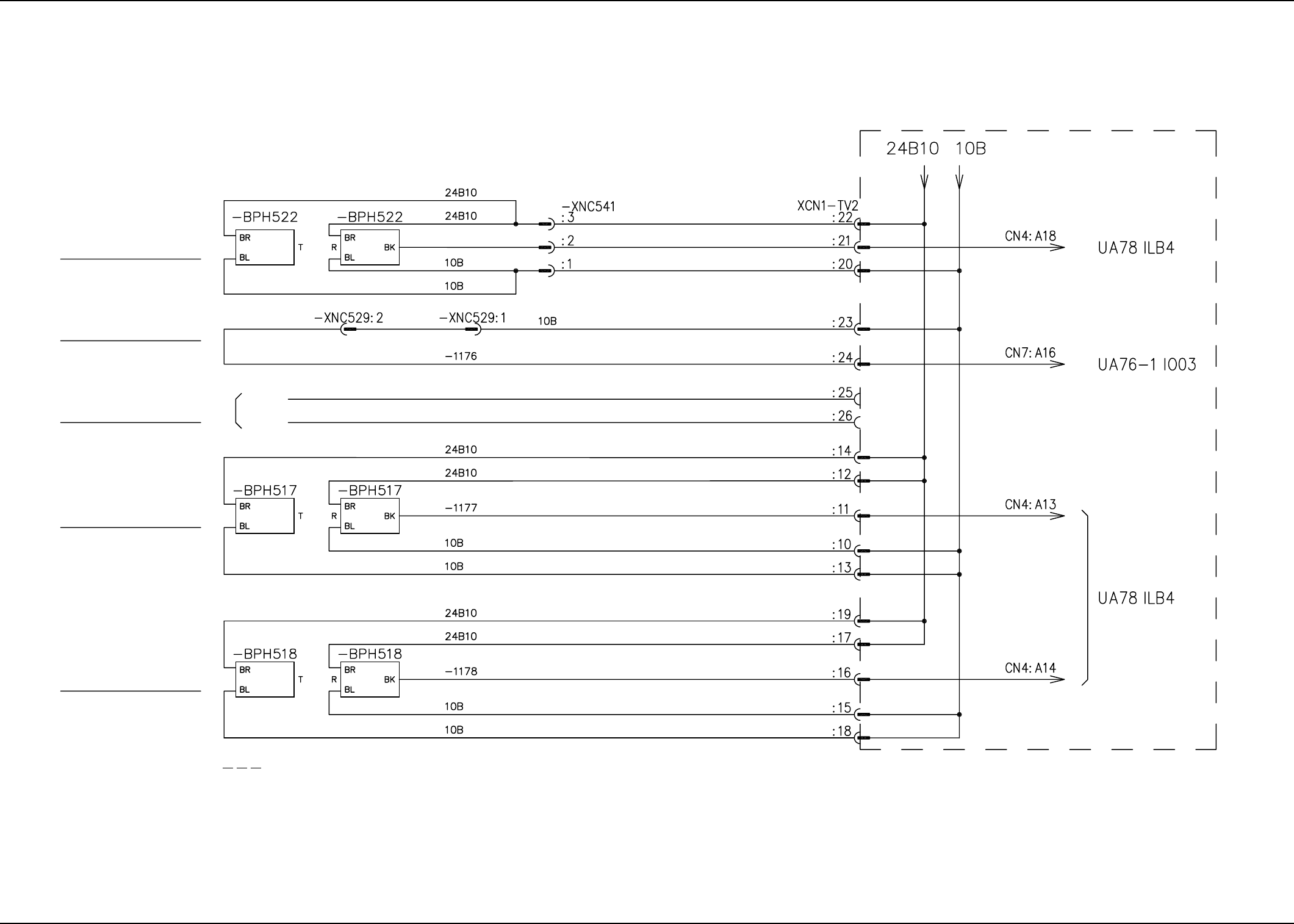
AHI01EGP
Note: (a) Surrounded by (broken line) are the wires connected to the main machine.
Mispicked Component
Detection (High)
Traverse 2 Connection
Check
Not Available
(Insulation)
Mispicked Component
Detection (Lower)
Mispicked Component
Detection (Upper)
Note (a)
0311-002 C(M756WTV--2103) 5-20
Tray 30 Steps Traverse Connection Diagram (2)
4.2 Electric Circuit Diagram for Each Section