OM-1078-002.pdf - 第25页
4. Safety-Related Features 4. Safety-Related Features This session describes the safety switches and module protection sen- sors. 4 . 1 Safety Switches and Sensors The safety switches and sensors work to stop the dangero…
No. Warning Labels and Description
*5
Description
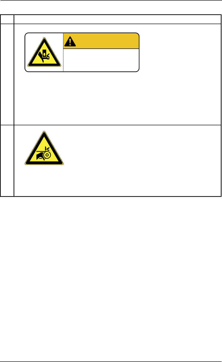
• Pay attention to the moving mechanisms. Otherwise, you may be
trapped in the moving mechanism, causing a major injury.
• When a door is opened or closed, be sure to hold the grip firmly and
slowly move the door up or down. Otherwise, your hand may be
trapped in the moving mechanisms, causing a major injury.
*6
Description
• Pay attention to the moving mechanisms. Otherwise, part of your body may be trapped
in the moving mechanisms.
3.2 Warning Labels and Description
Table X2
0204-002 22
AHI01EGP
WARNING
Moving Mechanisms!
4. Safety-Related Features
4. Safety-Related Features
This session describes the safety switches and module protection sen-
sors.
4.1 Safety Switches and Sensors
The safety switches and sensors work to stop the dangerous moving
mechanisms of the machine whenever an error is detected in the ma-
chine.
••
••
• The safety switches and sensors are set active on the machine side
(hardware), not by any software.
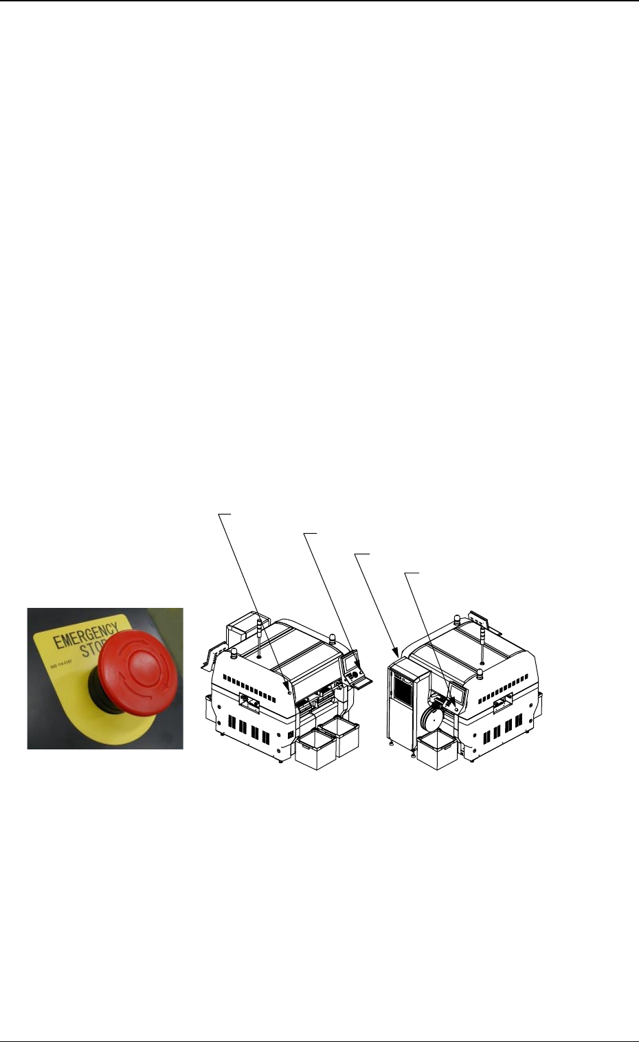
4.1.1 [EMERGENCY STOP] Switches
The multi-layer tray feeder is not provided with any [EMERGENCY STOP]
switches.
The [EMERGENCY STOP] switches of the main machine are com-
monly used for this feeder.
Press one of the [EMERGENCY STOP] switches to immediately stop
the machine in an emergency.
The power is turned off and the machine stops immediately.
0311-003 23 AHI01EGP
Fig. X18
[EMERGENCY STOP] Switch
Fig. X19
[EMERGENCY STOP] Switch (1)
[EMERGENCY STOP] Switch (2)
[EMERGENCY STOP] Switch (4)
[EMERGENCY STOP] Switch (3)
Front Side of Machine
Rear Side of Machine
Table X6
Button Name Symbol Countermeasures
[EMERGENCY STOP]
Button (1) (Rear Side)
[EMERGENCY STOP]
Button (2) (Rear Side)
[EMERGENCY STOP]
Button (3) (Front Side)
[EMERGENCY STOP]
Button (4) (Front Side)
When one of the left buttons is pressed, the following
measures are taken.
• All power sources for loads are shut off.
• Power to the motors excluding those for the vacuum
pump and the cooling fan is shut off.
Note: Power to the motors for the beam X/Y axis,
the traverse and elevator shafts of the multi-
layer tray feeder is shut off in 1 second after
the [EMERGENCY STOP] button is pressed.
• 24 V load power in the solenoid valve system ex-
cluding the solenoid valves for component picks and
the control power sources such as those for the
sensors is shut off.
Note: The load power for the safety doors, the so-
lenoids for electromagnetic locks, and the
solenoid valve for tape feed is shut off in 1
second after the [EMERGENCY STOP] but-
ton is pressed.
SPB31
SPB32
SPB33
SPB34
4.1 Safety Switches and Sensors
0204-002 24 AHI01EGP