OM-1078-002.pdf - 第26页
T able X6 Button Name Symbol Countermeasures [EMERGENCY STOP] Button (1) (Rear Side) [EMERGENCY STOP] Button (2) (Rear Side) [EMERGENCY STOP] Button (3) (Front Side) [EMERGENCY STOP] Button (4) (Front Side) When one of t…
4. Safety-Related Features
4. Safety-Related Features
This session describes the safety switches and module protection sen-
sors.
4.1 Safety Switches and Sensors
The safety switches and sensors work to stop the dangerous moving
mechanisms of the machine whenever an error is detected in the ma-
chine.
••
••
• The safety switches and sensors are set active on the machine side
(hardware), not by any software.
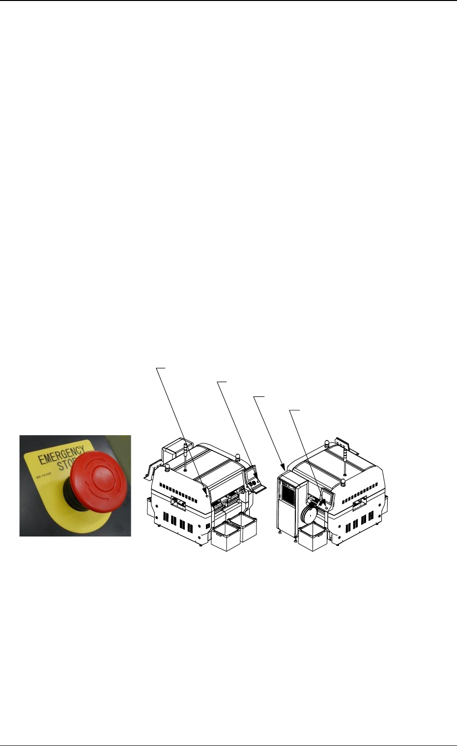
4.1.1 [EMERGENCY STOP] Switches
The multi-layer tray feeder is not provided with any [EMERGENCY STOP]
switches.
The [EMERGENCY STOP] switches of the main machine are com-
monly used for this feeder.
Press one of the [EMERGENCY STOP] switches to immediately stop
the machine in an emergency.
The power is turned off and the machine stops immediately.
0311-003 23 AHI01EGP
Fig. X18
[EMERGENCY STOP] Switch
Fig. X19
[EMERGENCY STOP] Switch (1)
[EMERGENCY STOP] Switch (2)
[EMERGENCY STOP] Switch (4)
[EMERGENCY STOP] Switch (3)
Front Side of Machine
Rear Side of Machine
Table X6
Button Name Symbol Countermeasures
[EMERGENCY STOP]
Button (1) (Rear Side)
[EMERGENCY STOP]
Button (2) (Rear Side)
[EMERGENCY STOP]
Button (3) (Front Side)
[EMERGENCY STOP]
Button (4) (Front Side)
When one of the left buttons is pressed, the following
measures are taken.
• All power sources for loads are shut off.
• Power to the motors excluding those for the vacuum
pump and the cooling fan is shut off.
Note: Power to the motors for the beam X/Y axis,
the traverse and elevator shafts of the multi-
layer tray feeder is shut off in 1 second after
the [EMERGENCY STOP] button is pressed.
• 24 V load power in the solenoid valve system ex-
cluding the solenoid valves for component picks and
the control power sources such as those for the
sensors is shut off.
Note: The load power for the safety doors, the so-
lenoids for electromagnetic locks, and the
solenoid valve for tape feed is shut off in 1
second after the [EMERGENCY STOP] but-
ton is pressed.
SPB31
SPB32
SPB33
SPB34
4.1 Safety Switches and Sensors
0204-002 24 AHI01EGP
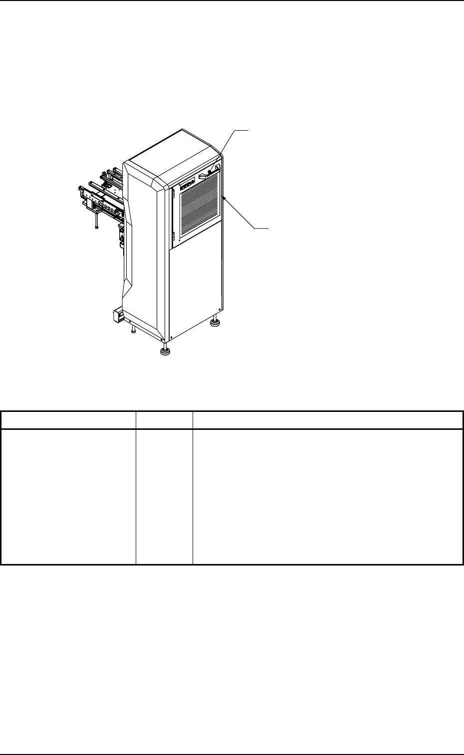
4.1.2 [Safety Door Electromagnetic Lock] Switch
When the LED of the [READY] button is ON, the safety door is locked
electromagnetically, making it impossible to open the door.
When the LED of the [READY] button is OFF, the safety door is un-
locked.
Switch Name Symbol Countermeasures
[Safety Door
Electromagnetic Lock]
Switch
Fig. X20
Table X7
[Safety Door Electromagnetic Lock]
Switch
Safety Door
• When the LED of the [READY] button is ON, the safety
door cannot be opened because it is locked by the
electromagnetic lock switch.
• When the safety door has opened due to the break-
down of the electromagnetic lock switch, etc., with
the machine in operation, the power to the elevator
shaft is shut off.
(Stop in Error Condition)
YSOL501
0311-003 25
AHI01EGP
4.1 Safety Switches and Sensors