OM-1078-002.pdf - 第40页
(2) Rear Side of Machine Fig. A3 Rear View 031 1-002 1-4 AHI01EGP 1.2 Name and Function of Each Section Rack T raverse
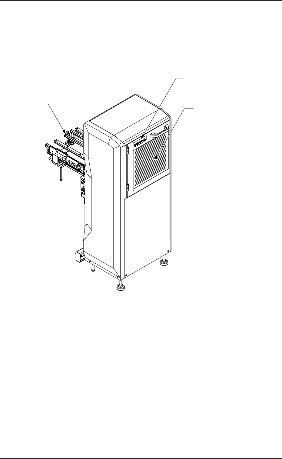
1.2 Name and Function of Each Section
1.2.1 General View
(1) Front Side of Machine
Fig. A2 Front View
1.2 Name and Function of Each Section
0311-002 1-3 AHI01EGP
T
raverse
Operation Switches
Safety Door
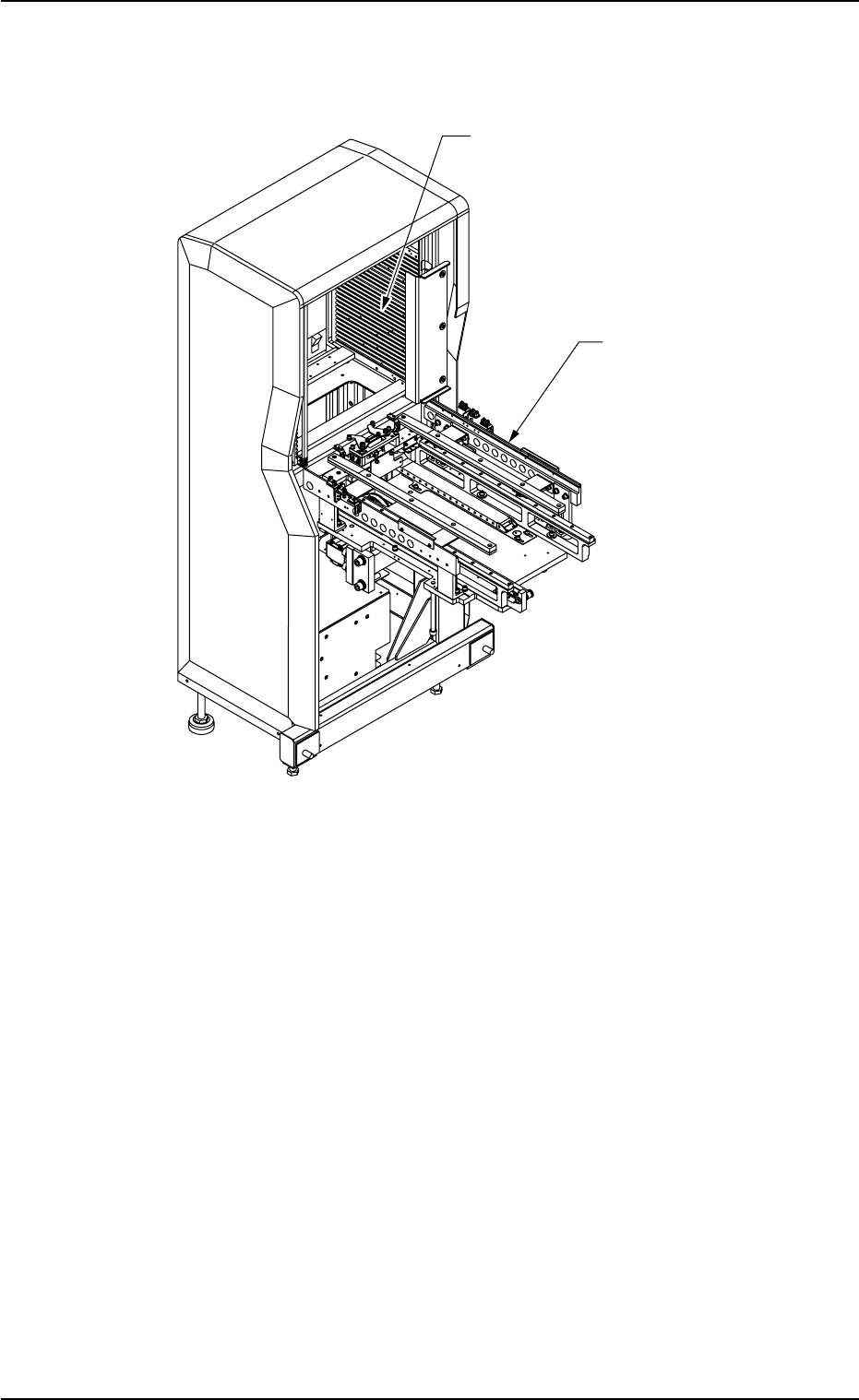
(2) Rear Side of Machine
Fig. A3 Rear View
0311-002 1-4
AHI01EGP
1.2 Name and Function of Each Section
Rack
Traverse
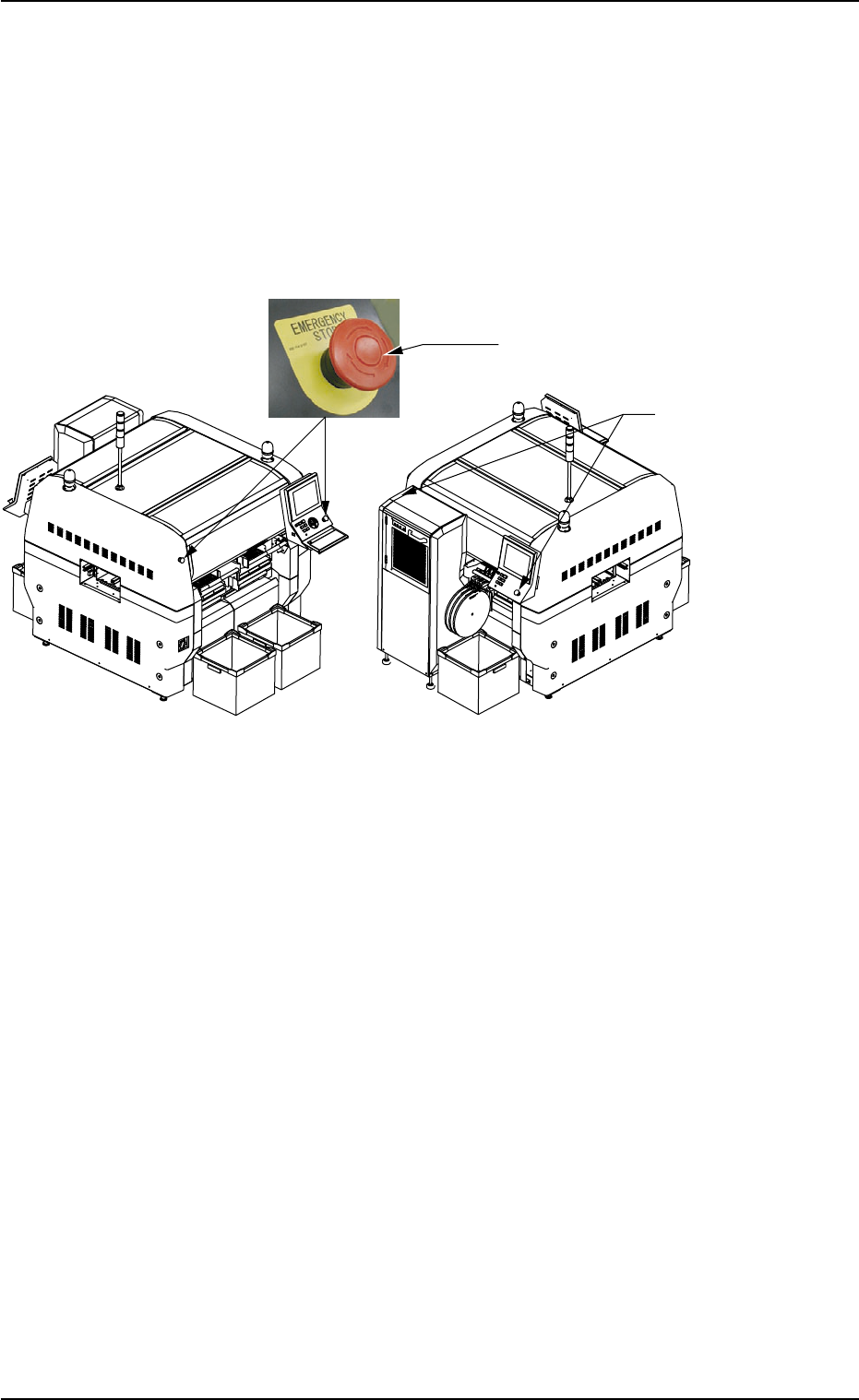
1.2.2 Safety Devices
(1) [EMERGENCY STOP] Switches
The multi-layer tray feeder is not provided with any [EMERGENCY
STOP] switches.
The [EMERGENCY STOP] switches of the main machine are com-
monly used for this feeder.
Fig. A4
The [EMERGENCY STOP] switches can be used to stop machine op-
eration in an emergency.
When one of the [EMERGENCY STOP] switches of the main machine
is pressed, the power to the feeder is turned off and the feeder stops
immediately.
When the power is turned off, the LED of the [POWER ON] button on
the operation panel illuminates in red.
• Locking the [EMERGENCY STOP] Switch
When an [EMERGENCY STOP] switch is pressed, all power is shut
off, the machine stops running, and the [EMERGENCY STOP] switch
is locked to avoid any careless power re-supply to the machine.
• Unlocking the [EMERGENCY STOP] Switch
Before re-supplying power to the machine, check and remove the
cause of emergency stop and inspect each section of the machine.
Then, unlock the [EMERGENCY STOP] switch.
To unlock the button, turn the button clockwise.
0311-003 1-5
AHI01EGP
Front Side of Machine Rear Side of Machine
[EMERGENCY STOP] Switch
[EMERGENCY STOP]
Switch
1.2 Name and Function of Each Section