OM-1078-002.pdf - 第43页
(2) Operation Switches The switches for machine operations are collectively arranged. Fig. A6 Operation Switches *1 ELEV . POWER This switch indicates whether or not the power to the elevator axis is supplied. ON: The po…
1.2.3 Equipment for Operations
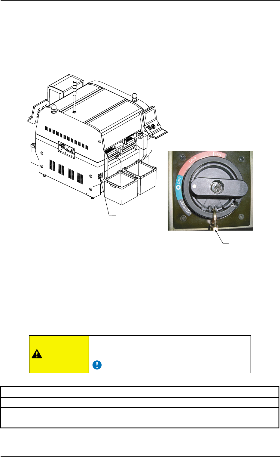
(1) Power Breaker
This multi-layer tray feeder is not provided with any power breaker.
The power breaker of the main machine is commonly used for this
feeder.
Fig. A5
The power breaker is provided to supply or shut off power to the ma-
chine.
The power breaker can be locked with a padlock.
Refer to "1.7.2 Locking the Power Breaker with the Padlock" in "Section
3 Outline of Automatic Operation" (the instruction manual (Vol. 1) of the
main machine) for the procedure to lock the breaker.
Before maintenance, etc., be sure to turn off the power
breaker and lock it with the padlock for safety purposes.
Table A1
Symbols/Names Functions
{ (OFF) Shut-Down Operation (Fig. A5)
tripped Power Breaker Tripped
| (ON) Power Supply
0311-003 1-6
AHi01EGP
Power Breaker
Padlock
1.2 Name and Function of Each Section
CAUTION
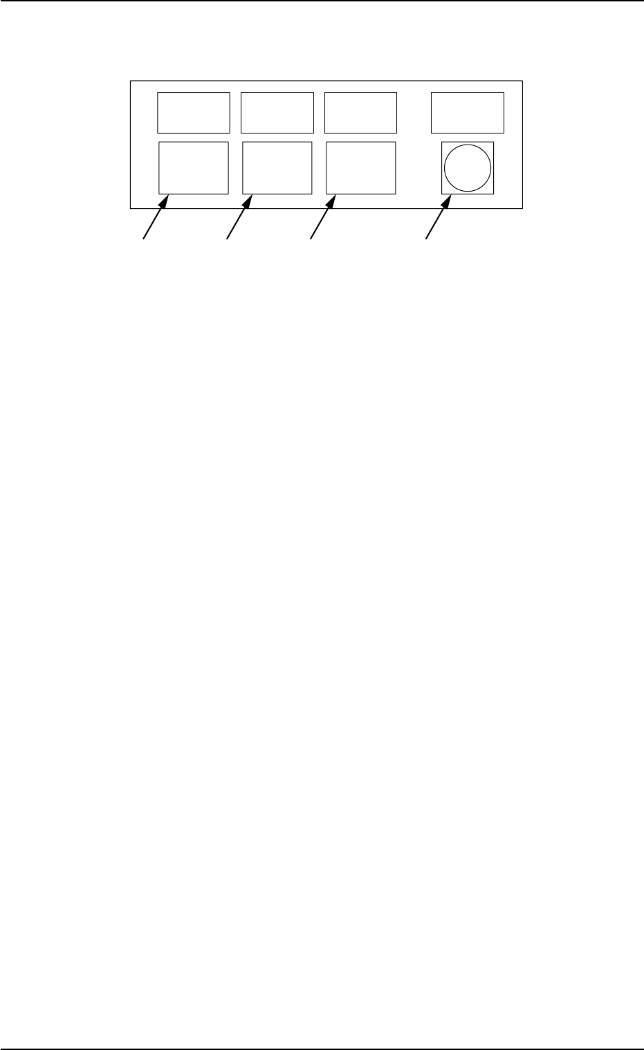
(2) Operation Switches
The switches for machine operations are collectively arranged.
Fig. A6 Operation Switches
*1 ELEV. POWER
This switch indicates whether or not the power to the elevator
axis is supplied.
ON: The power is supplied to the elevator axis.
*2 [HOME POSITION] Button
When this button is pressed, the elevator axis is zeroed or moved
to the replacement position (home position).
ON : This indicates that the elevator axis is located at
its origin.
ON and OFF : This indicates that the elevator axis is being ze-
roed.
OFF : This indicates that the elevator axis is not located
at its origin.
*3 [READY] Button
This button is used to tell the main machine that the tray is set
ready to be replaced with another one.
ON : This indicates that the tray is already set ready
for the replacement.
ON and OFF : This indicates that the tray is being shifted to the
replacement mode.
OFF : This indicates that the tray is set in the replace-
ment mode.
*4 [ALL CHANGE] Button
This button is used to confirm the overall tray replacement for the
empty step (the step without any components).
ON : This indicates that the overall tray replacement
can be accepted.
OFF : This indicates that the overall tray replacement
cannot be accepted.
0204-002 1-7
AHI01EGP
ALL
ALL
READY
READY
CHANGE
CHANGE
HOME
HOME
POSITION
POSITION
POWER
POWER
ELEV.
ELEV.
*1
*2
*3
*4
1.2 Name and Function of Each Section
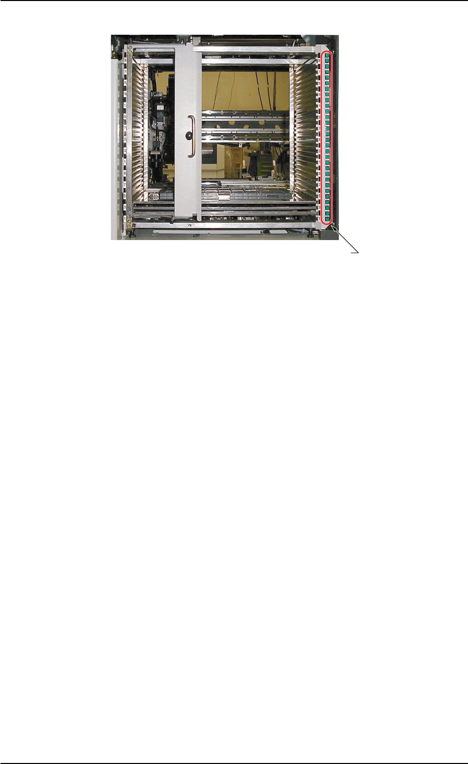
(3) [TRAY LOAD] Switch
Fig. A7
*1 [TRAY LOAD] Switch
When a program change operation is performed, the LED of the
switch in the step specified in the placement feeder location and
step data flickers, indicating that the tray should be loaded addi-
tionally with components.
When the [TRAY LOAD] switch is pressed after component re-
plenishment, the LED is kept "ON", indicating that the compo-
nent replenishment is completed.
ON : This indicates that the tray is already loaded newly
with components.
OFF : This indicates that the tray is not used.
ON and OFF : This indicates that the tray is short of compo-
nents.
0204-002 1-8
AHI01EGP
*1 [TRAY LOAD] Switch
1.2 Name and Function of Each Section