OM-1078-002.pdf - 第45页
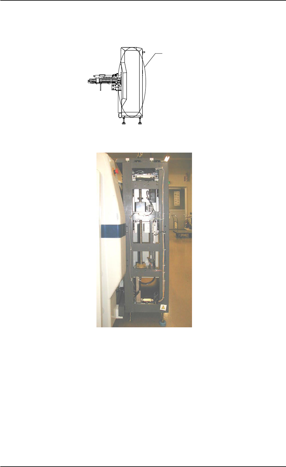
1.2.4 Main Units (1) Elevator Section Fig. A8 Fig. A9 This section is provided with a mechanism that moves the rack up and down. 031 1-002 1-9 AHI01EGP 5 5 Elevator Section 1.2 Name and Function of Each Section
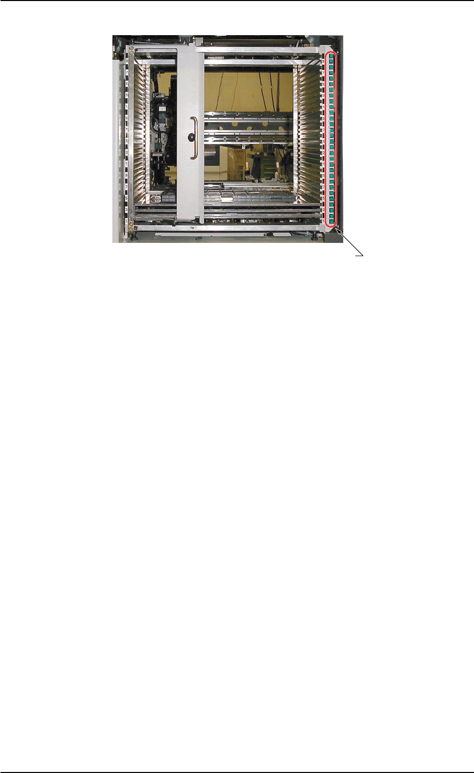
(3) [TRAY LOAD] Switch
Fig. A7
*1 [TRAY LOAD] Switch
When a program change operation is performed, the LED of the
switch in the step specified in the placement feeder location and
step data flickers, indicating that the tray should be loaded addi-
tionally with components.
When the [TRAY LOAD] switch is pressed after component re-
plenishment, the LED is kept "ON", indicating that the compo-
nent replenishment is completed.
ON : This indicates that the tray is already loaded newly
with components.
OFF : This indicates that the tray is not used.
ON and OFF : This indicates that the tray is short of compo-
nents.
0204-002 1-8
AHI01EGP
*1 [TRAY LOAD] Switch
1.2 Name and Function of Each Section
1.2.4 Main Units
(1) Elevator Section
Fig. A8
Fig. A9
This section is provided with a mechanism that moves the rack up and
down.
0311-002 1-9
AHI01EGP
55
Elevator Section
1.2 Name and Function of Each Section
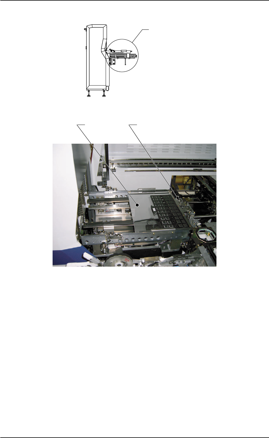
(2) Traverse Section
Fig. A10
Fig. A11
This section is provided with a mechanism that draws out a pallet from
the rack.
0311-003 1-10
AHI01EGP
Pallet Chuck
Pallet
1.2 Name and Function of Each Section
5
Traverse Section