OM-1078-002.pdf - 第49页
2. Basic knowledge of Operation 031 1-002 1-13 AHI01EGP 2. Basic knowledge of Operation 2.1 Basic Operations Refer to "1.2 T ouch Screens" in "Section 2" (the instruction manual (V ol. 1) of the main …
1.3 Mechanism of Component Supply
(1) A tray (pallet) is drawn out to the traverse section from the rack
stored in the elevator section by the traverses according to the pat-
tern program data.
(2) The placement heads of the main machine take out the compo-
nents from the tray drawn out to the traverse section.
(3) The component recognition camera captures the images of the com-
ponents taken out by the placement heads and the images are rec-
ognized to correct the deviations in the pickup positions for accu-
rate component placement.
A component discharge operation is performed when a pickup er-
ror or a recognition error is detected after component recognition.
(4) The tray in the traverse section is stored in the elevator and another
tray is drawn out to the traverse section according to the pattern
program data.
When the components to be placed subsequently are in the same
tray, the tray stays on standby in the traverse section.
(5) Steps (2) through (4) are repeated.
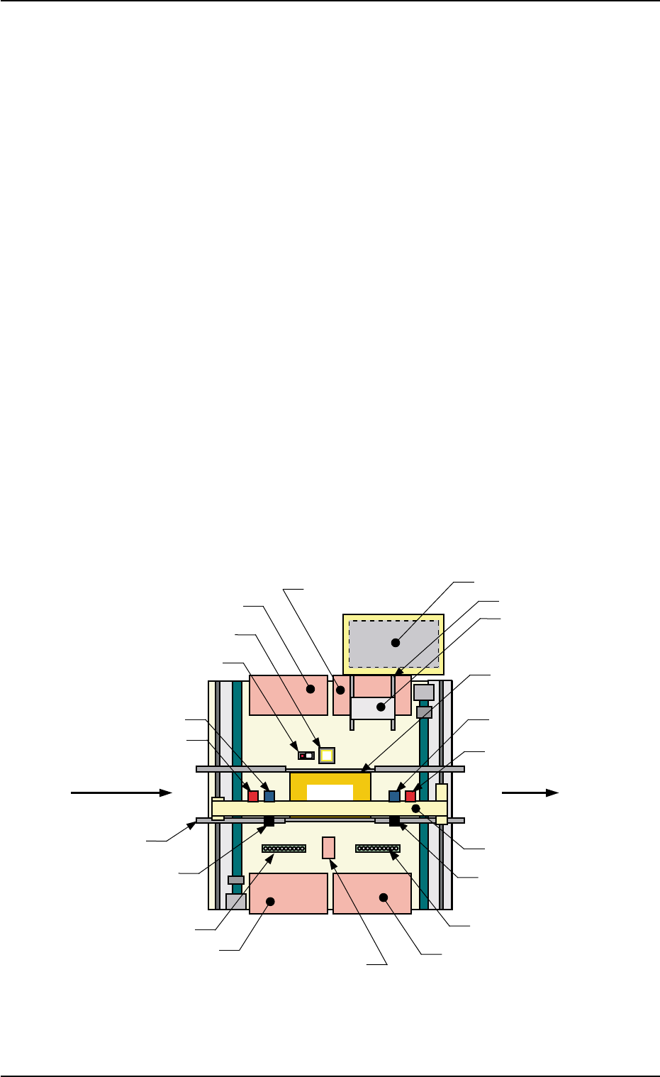
Fig. A14 Rough View (P.C.B. Transfer Direction: Left to Right)
1.3 Mechanism of Component Supply
0204-002 1-12 AHI01EGP
Transfer Conveyor
P.C.B.
Feeder Base #4
Feeder Base #1
Feeder Base #3
Back Light Plate
Nozzle Stocker B2
Nozzle Stocker B1
Head #1
Movable Camera 1
Fixed Camera A1
X/Y Beam
P.E.C. Recognition Camera 2
Head #2
Movable Camera 2
(Input Machine)
P.C.B. Flow Direction
(Output Machine)
Traverse
Tray
Feeder Base #2
P.E.C. Recognition
Camera 1
Elevator
Component Storage Box
(Front Side of Machine)
P.C.B. Positioning Section
(P Conveyor)

2. Basic knowledge of Operation
0311-002 1-13 AHI01EGP
2. Basic knowledge of Operation
2.1 Basic Operations
Refer to "1.2 Touch Screens" in "Section 2" (the instruction manual (Vol.
1) of the main machine) for details.
This tray feeder is not provided with any touch screen.
The touch screen of the main machine is commonly used.
2.2 Starting or Exiting from the Application
2.2.1 Getting Started
Refer to "2. Starting or Exiting from the Application" in "Section 2" (the
instruction manual (Vol. 1) of the main machine) for details.
This tray feeder is not provided with any [POWER ON] button.
The [POWER ON] button of the main machine is commonly
used.
Note
Note
3. Outline of Automatic Operation
0311-003 1-14 AHI01EGP
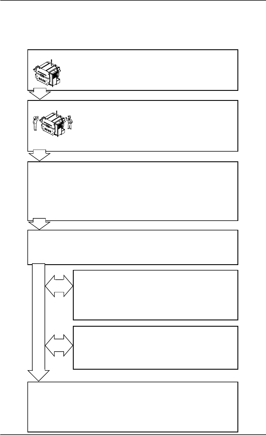
3. Outline of Automatic Operation
3.1 Normal Automatic Operation
Flow of Automatic Operation
Program Change Operation
Refer to "Section 2 Operation (Supervisor)" for details.
Inspections Work before Operation
Refer to the following items in "Section 3" (the instruc-
tion manual (Vol. 1) of the main machine) for details.
1.1.1 Confirmation of Power Supply and Air Pressure
1.1.2 Confirmation of Safety Doors and Feeder Base
Pullout Prevention Bars
Preparation before Operation
Refer to the following items for details.
3.3.1 Power ON Operation
3.3.2 "AUTO OPERATION" Windows and Zeroing
of Each Device
3.3.3 Preparation for Pallets
3.3.7 Preparation for P.C.B.’s
Start of Automatic Operation
Refer to the following item in "Section 3" (the instruc-
tion manual (Vol. 1) of the main machine) for details.
1.3 Start of Automatic Operation
Stop and Re-Start Operation of Automatic Operation
Refer to the following items for details.
3.5.1 Replenishment of Components
3.5.2 Replenishment of P.C.B.’s
3.5.3 Temporary Stop (Pause) with [STOP] Button
3.5.4 Stop Operation by Selection of "Auto Stop Mode"
Interruption of Automatic Operation
Refer to the following item in "Section 3" (the instruc-
tion manual (Vol. 1) of the main machine) for details.
1.5.1 Interruption with [CANCEL] Button
1.5.2 Interruption with [EMERGENCY STOP] Switch
End of Automatic Operation
Refer to the following items in "Section 3" (the instruc-
tion manual (Vol. 1) of the main machine) for details.
1.6.1 Stop of Automatic Operation
1.7.1 Procedure for Shut-Down Operation
1.7.2 Locking the Power Breaker with the Padlock
Fig. A15
Fig. A16