OM-1078-002.pdf - 第96页
5.3.3 "T ray T each Pick-Up Pos. [Comp. Center Pos.]" Sheet This sheet makes it possible to perform a teaching operation to align the center of the vacuum nozzle with the center of the component to be supplied …

• Sheet Composition
*1 [Tray Teach Pick-Up Pos. [Comp. Center Pos.]] Button
When the center of the vacuum nozzle must be aligned with the
center of the component to be supplied from the tray feeder through
a teaching operation, press this button. The "Tray Pick-Up Pos.
[Comp. Center Pos.]" sheet appears.
Refer to "5.3.3 "Tray Teach Pick-Up Pos. [Comp. Center Pos.]"
Sheet" for details.
*2 [Tray Teach Ecc. Pick-Up Pos. [Pickup Loc. Adj] Button
When the component supplied from the tray feeder cannot be picked
up normally at the center and the eccentric pick-up correction posi-
tion must be taught, press this button. The "Tray Teach Ecc. Pick-
Up Pos. [Pickup Loc. Adj]" sheet appears.
Refer to "5.3.4 "Tray Teach Ecc. Pick-Up Pos. [Pickup Loc. Adj]"
Sheet" for details.
*3 [Tray Matrix Pitch XY-Side Length] Button
When the matrix pitch X and Y, the side lengths, and the positional
offsets must be taught for the tray, press this button. The "Tray Ma-
trix Pitch XY-Side Length" sheet appears.
Refer to "5.3.5 "Tray Matrix Pitch XY-Side Length" Sheet" for details.
0204-001 2-22
AHI01EGP
5.3 "TEACHING" Window (Submenu)
5.3.3 "Tray Teach Pick-Up Pos. [Comp. Center Pos.]" Sheet
This sheet makes it possible to perform a teaching operation to align the
center of the vacuum nozzle with the center of the component to be
supplied from the multi-layer tray feeder.
• Sheet Layout
When the [Tray Teach Pick-Up Pos. [Comp. Center Pos.]] button is
pressed in the "Pick-Up Location" tab sheet , the following sheet ap-
pears.
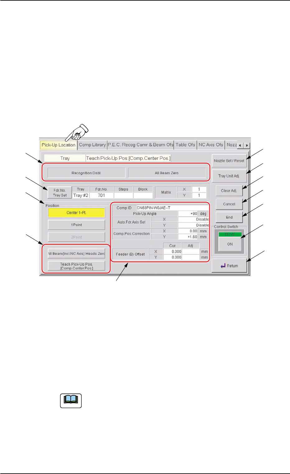
Fig. B11 "Tray Teach Pick-Up Pos. [Comp. Center Pos.]" Sheet
• Sheet Composition
*1 Set Status
When the "P.E.C. Dsbl." or the "Comp. Recognition Dsbl." check
box in the "Test Run" tab sheet is turned on (checked), the back-
ground color of "Recognition Dsbl." turns light red (No background
color in normal cases).
No recognition processing is made even if a teaching op-
eration is performed when each check box is turned on
(checked) in the "Test Run" tab sheet. Therefore, various
teaching operations will get incorrect results.
When all beams are zeroed completely, the background color of "All
Beam Zero" turns green. Otherwise, the background has no color.
0311-002 2-23
AHI01EGP
5.3 "TEACHING" Window (Submenu)
*1
*6
*7
*8
*9
*10
*11
*12
*4
*5
*3
*2
Note

(a) When each section is not set up and a teaching opera-
tion is performed, note that the offset values may not
be taught correctly.
(b) Before performing a teaching operation, be sure to zero
all beams.
*2 Fdr. No. Tray Set
Set the feeder No. to be taught.
When the [Fdr. No.] button is pressed, the "Feeder No. Set" sheet
appears.
Refer to "5.3.6 "Feeder No. Set" Sheet" for details.
*3 "Position" Group Box
The following buttons are provided in this group box.
[Center 1-Pt.] Button
When the [ENABLE] button on the operation panel is pressed in 2
seconds after this button and the [ON] button (entitled "MOVE"), the
P.E.C. recognition camera moves to the component center position
(Design Position + Feeder (B) Offset) of the pertinent feeder, mak-
ing it possible to capture an image.
Proceed to the operation of the pointing device and execute the
manual alignment operation.
[1Point] and [2Point] Buttons
These buttons are used to align the component with 2 diagonally-
located points.
Use this function when the maximum outside dimensions of the
component exceed "10 × 10 mm" (when the "Recognition" window
cannot cover the whole image of the component).
*4 Mode Selection Buttons
Various actions can be selected.
The following buttons are provided.
[All Beam (Incl. NC Axis) Heads Zero] Button
When this button is pressed, all X/Y beams are zeroed.
When the [ENABLE] button on the operation panel is pressed in 2
seconds after this button and the [ON] button (entitled "MOVE"), the
zeroing operation starts.
[Teach Pick-Up Pos. [Comp. Center Pos.]] Button
The corresponding sheet makes it possible to perform a teaching
operation to align the component center with the nozzle center.
*5 Offset Values
Displayed are the current values and the adjusted ones after teach-
ing.
0311-002 2-24
AHI01EGP
5.3 "TEACHING" Window (Submenu)
Note