RS-1_instruction manual.pdf - 第1019页
Part 2 D etaile d Descript ion of E ach Functi on Chapter 12 Handling th e Optional Device s 12 - 135 12.19.2 Specifications (1) Required part s and softwar e - US B memor y contain ing a nozzl e informat ion f ile that …
Part 2 Detailed Description of Each Function Chapter 12 Handling the Optional Devices
12-134
12.19 Gripper Nozzle
This nozzle is designed to pick up and/or place on a board a component whose top has no
picked-up area, and it is available to laser and vision recognition.
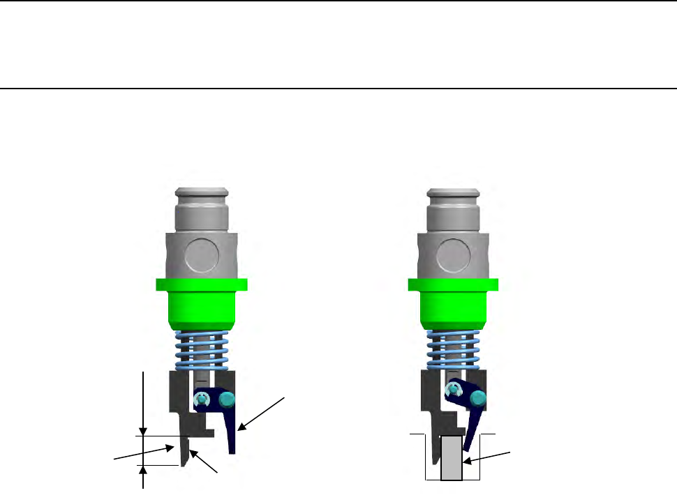
12.19.1 Features
The gripper nozzle uses its “fixed arm” and “swing arm” together exclusively to pick up and/or
place a component whose topside has no picked-up area from the component side. Its grip
strength is appropriate enough to pick up/place a component stably.
① Fixed arm
② Swing arm
Position against a
component is pushed
Length of a lug
①
②
Component
Part 2 Detailed Description of Each Function Chapter 12 Handling the Optional Devices
12-135
12.19.2 Specifications
(1) Required parts and software
- USB memory containing a nozzle information file that is supplied to the customer
together with the nozzle in the same package
- Gripper nozzles that are appropriate for the shape and size of each component and the
shape of a feeder unit (such as tape and tray)
(See “(5) Applicable components and packaging style.”)
(2) Method
Centering method: Laser
(3) Component placement precision
Component placement precision : ± 0.3 mm or less (3 σ)
Note that the attained precision may vary depending on the shape of a component.
When the system places a component whose portion to be aligned with laser has an
edge, whose molded part has a burr, or whose portion to be inspected with the system
cannot be fixed to a pick-up device, the precision described above cannot be attained.
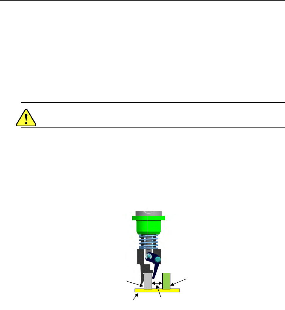
(4) Limited adjacent components
When the system places a component, a gripper swing arm opens, so it may be in contact
with an adjacent component.
Therefore, there are the following two restraints on operations of a gripper nozzle:
- The height of a component to be placed with a gripper nozzle should be 3 mm or higher
than that of adjacent components.
- The side of a component to be held with the swing arm of the gripper nozzle should be
far from adjacent components by 4 mm or more.
(See the figure below.)
(5) Applicable components and packaging style
Applicable components:
• Connectors
(the top side cannot be picked up with a standard nozzle)
• Lead pitch (1 mm or wider)
• Weight: 5 g or less
(This value is subject to change depending on the shape of a component.)
• There should be a flat area on the top of a component against which the fixed arm
can be pushed. (to prevent a component from inclining when the X-Y axes moves)
Packaging style:
• Taping and tray
Component B
Component A
Note: Components A and B should
another by at least 4mm.
Board
Part 2 Detailed Description of Each Function Chapter 12 Handling the Optional Devices
12-136
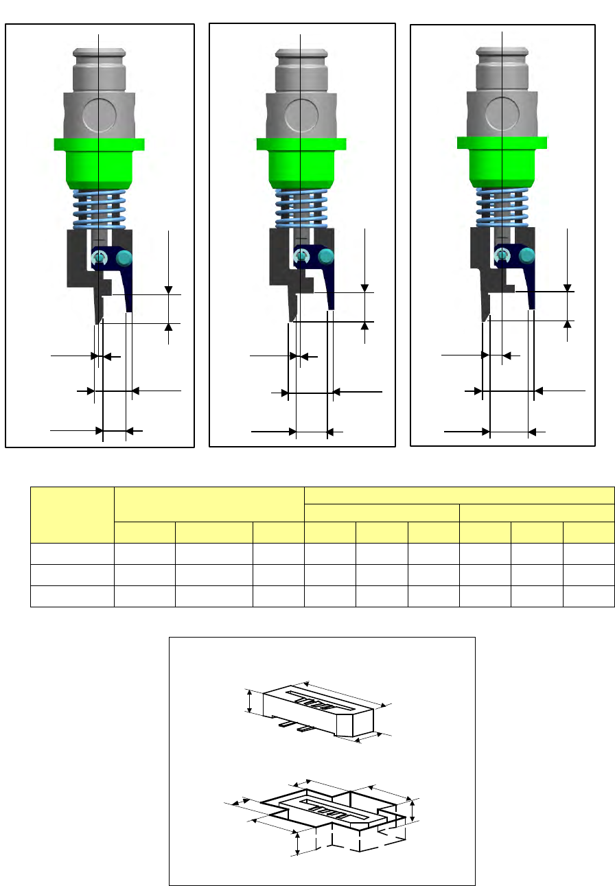
- Applicable component and applicable package size
・Applicable component and package size
Nozzle
number
Applicable components
Packaging style (Dimensions of an embossed part)
Fixed arm side
Swing arm side
X
Y
H
A
B
C
D
E
F
7689
6
~
0.8
~
2.2
5
~
1.5
~
5.6
~
4
~
3
~
5.6
~
2.5
~
7690
6
~
1.8
~
3.2
5
~
1.5
~
5.6
~
4
~
3
~
5.6
~
2.5
~
7691
6
~
2.8
~
4.2
5
~
1.5
~
5.6
~
4
~
3
~
5.6
~
2.5
~
H
X
Y
A
D
E
B
F
C
0.5
4.7
2.8
3.5
No. 7689 nozzle
0.5
5.7
3.8
3.5
No. 7690 nozzle
1.5
6.7
4.8
3.5
No. 7691 nozzle