RS-1_instruction manual.pdf - 第1041页
Pa r t 2 D et ail ed Des c r i p ti on of Each Function C hapter 1 3 Supp l em en t ar y I nf o rm ati on f or C r eating a Production P rogra m 13 - 18 F il e type of Produ ction Progr ams 13. 4 Read enable file ty pe t…

Part 2 Detailed Description of Each Function Chapter 13 Supplementary Information for
Creating a Production Program
13-17
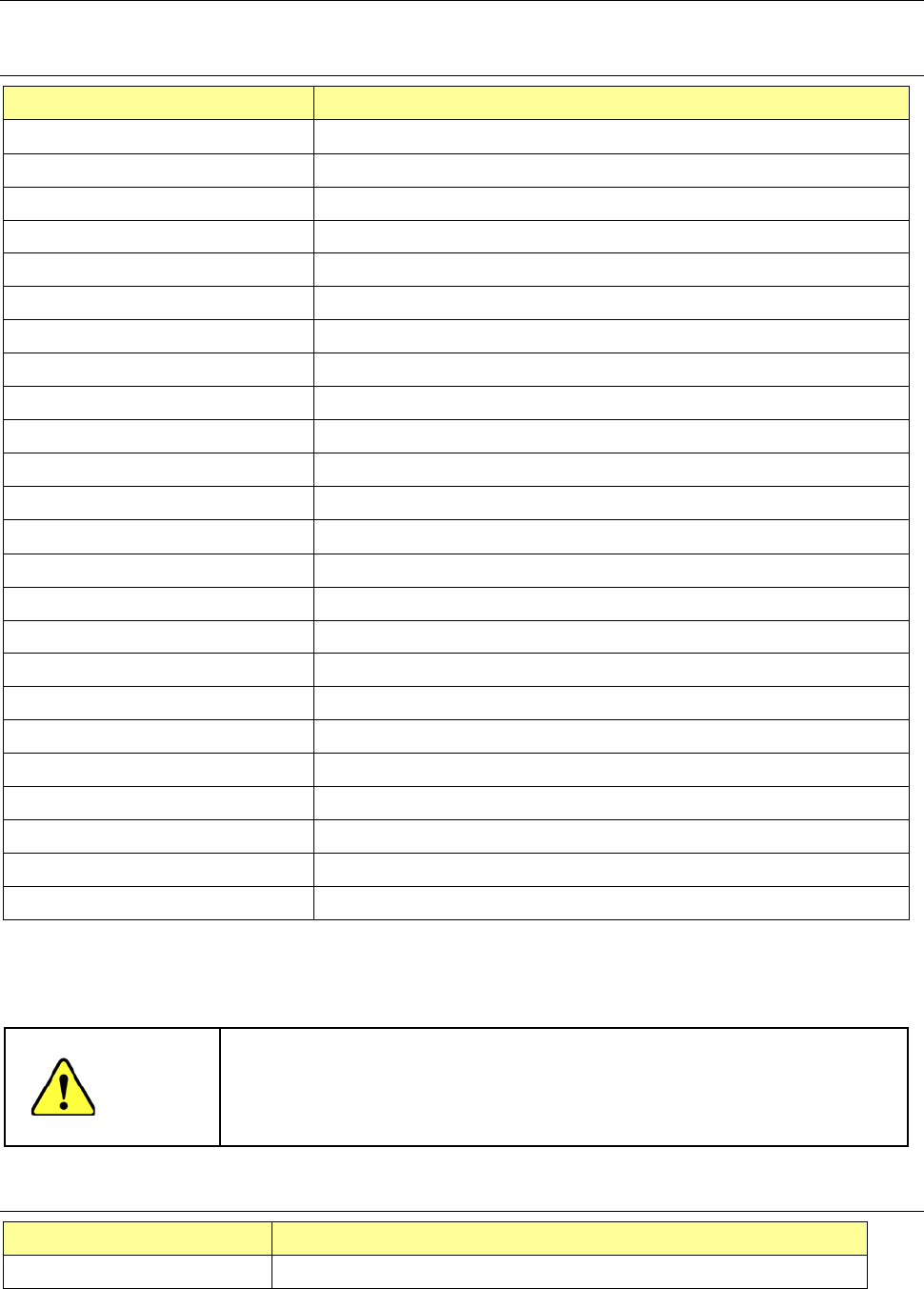
Functions available to each user level 13.3
Menu and
button
Function Operator Programmer Manager Maintenance
Service
Engineer
File menu
New × ○ ○ ○ ○
Open ○ ○ ○ ○ ○
Save ○ ○ ○ ○ ○
Save as ○ ○ ○ ○ ○
Print × ○ ○ ○ ○
Error log record display ○ ○ ○ ○ ○
Program
editing menu
Production program editing × ○ ○ ○ ○
Preparation/
adjustment
menu
Control data management × × ○ ○ ○
Machine information saving ○ ○ ○ ○ ○
Image information saving × ○ ○ ○ ○
Machine operation
information
× ○ ○ ○ ○
Return-to-origin ○ ○ ○ ○ ○
Production
menu
PWB production ○ ○ ○ ○ ○
Trial run ○ ○ ○ ○ ○
Dry run ○ ○ ○ ○ ○
Idle mode ○ ○ ○ ○ ○
Warming up ○ ○ ○ ○ ○
Machine
setting menu
Machine setup × × ○ ○ ○
Operation option × ○ ○ ○ ○
Maintenance
menu
Manual control × × ○ ○ ○
Mech. Parameter setting × × × × ○
MS parameter setting × × × × ○
Maintenance log × × ○ ○ ○
Self-diagnostic function ○ ○ ○ ○ ○
FCS × × ○ ○ ○
Bend correction × × × × ×
Environment
setting menu
User level
change/environment setting
○ ○ ○ ○ ○
Production program initial
directory
○ ○ ○ ○ ○
Display language selection
setting
× × ○ ○ ○
Operating environment
setting
× × ○ ○ ○
Version information ○ ○ ○ ○ ○
Startup
menu
File management (Explorer) × ○ ○ ○ ○
Saf e removal of hardware ○ ○ ○ ○ ○
Date and time adjustment × × × ○ ○
Application
cut
Exit
○ ○ ○ ○ ○
Part 2 Detailed Description of Each Function Chapter 13 Supplementary Information for
Creating a Production Program
13-18
File type of Production Programs 13.4
Read enable file type table 13.4.1
Type name (extension) Explanation of program file
RS-1/1R type file (s01x) File created by RS-1/1R main unit
RX-7 type file (prd) File created by RX-7 main unit
RX-6/6B/6R type file (j01x) File created by RX-6
2050/2050R type file (e54) File created by 2050/2050R main unit
2060 type file (e46) File created by 2060 main unit
2070 type file (e47) File created by 2070/1070 main unit
2080 type file (e48) File created by 2080/2080R main unit
CX-1 type file (e56) File created by CX-1 main unit
FX-1/FX-1R type file (e51) File created by FX-1/FX1R main unit
FX-2 type file (X52) File created by FX-2 main unit
FX-3 type file (x01) File created by FX-3 main unit
2077 type file (X52) File created by FX-2 main unit
3010 type file (X11) File created by 3010 main unit
3020 type file (x21) File created by 3020/3020R
File divided by optimization (i01) File divided for machine #1 of line by Production support system
File divided by optimization (i02) File divided for machine #2 of line by Production support system
File divided by optimization (i03) File divided for machine #3 of line by Production support system
File divided by optimization (i04) File divided for machine #4 of line by Production support system
File divided by optimization (i05) File divided for machine #5 of line by Production support system
File divided by optimization (i06) File divided for machine #6 of line by Production support system
File divided by optimization (i07) File divided for machine #7 of line by Production support system
File divided by optimization (i08) File divided for machine #8 of line by Production support system
File divided by optimization (i09) File divided for machine #9 of line by Production support system
File divided by optimization (i10) File divided for machine #10 of line by Production support system
* The extension may be the same in the production program created by the mounter not listed in the
above "Explanation of program file", but please do not read it because RS-1/1R does not support it.
Example: JX 300 LED is the same as 2070 format file (e 47)
CAUTION
* Precautions on reading data
The 770, 775, 2077, RX-7 type file contains component names but no
contents of component data. For the files of a type other than RS-1/1R,
the pick data is selected automatically.
Save enable file type table 13.4.2
Type name (extension) Explanation of program file
RS-1/1R type file (s01x) File created by RS-1/1R

Part 2 Detailed Description of Each Function Chapter 13 Supplementary Information for
Creating a Production Program
13-19
Patterns which can be registered as the user defined template 13.5
1) Patterns which can be registered as the user defined template
1) Wiring pattern
2) Pad and land pattern where no screen is printed (no solder paste is put)
3) PWB marks other than JUKI standard marks (whole or part)
2) Notes on registration as the user defined template
Through hole and pier hole
Since the pattern generation process is different from the holing process, the same
positioning cannot be always achieved. (The hole position is undefined for a pattern.)
To register the template based on the through hole or pier hole, include the wiring pattern
around the hole.
3) Pattern which cannot be registered as the user defined template
1) Silk (character) pattern
Since the pattern and pad generation process is totally different from the silk printing
process, the placement position cannot be determined based on the silk print.
2) Pad and land pattern printed on the silk screen
The solder paste on the screen is in the form of grains, so lighting cannot be stable
depending on the environment or condition. The template matching is highly appropriate
for change of lighting conditions, but not for the change of polarity (positive and negative).
3) The similar pattern is located on the same recognition screen
4) The template whose difference between the brightness and the darkness is little.
5) Pattern whose scale (size) and/or angle changes
Especially if a part of the pattern is specified as the user defined template, change of the
scale affects the recognition accuracy. Therefore, specify the entire pattern as the user
defined template if possible.
The farther the gravity center of the template (as described above) is from the that of the
template, the more the angle change affects the recognition operation: the recognition
position is shifted. Set the user defined template so that the gravity center of the
template matches with the center of the template as correctly as possible.
When you press the camera button, white and black can be reversed. Accordingly, if the
mark is imaged in black for PWB, press the camera button to reverse while and black so
that the mark may be imaged in white. The mark reverse by the camera button is
enabled only when the scale frame is input.