RS-1_instruction manual.pdf - 第350页
Part 1 B asic O peration Chapter 4 Cr eating a Produc tion Progra m 4- 15 13) Clamp offs et (Board whose X - dimens ion of the “PWB dim ensions” exceeds th e regulated size (650 mm)) As the “Clamp O ffset ,” specify the …
Part 1 Basic Operation Chapter 4 Creating a Production Program
4-14
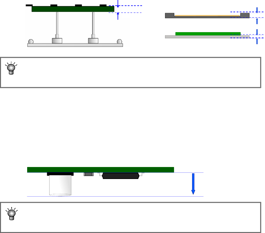
11) PWB thickness
Enter the thickness of a PWB. The value you entered here is used to determine how much
the system should move up the support table when it is centering a PWB.
If an incorrect value is entered, the support pin pushes the PWB too much, thereby
damaging the PWB, and the placement may lose uniformity because the support pin
does not touch the PWB.
12) Back height
Enter the height of the tallest component among the components placed on the back side of
a PWB (you have to enter a value that causes components on the back side not to interfere
with the support pin if components are placed on both sides of a PWB).
This value determines the waiting position of the support table during production.
If you enter a small value, the traveling distance of the support table becomes shorter,
reducing the production time a little.
(Approx. 0.25-second difference between the maximum height of 5 mm and 40 mm)
If a value is entered that is smaller than the component height on the back, the
support pin may hit the component during PWB transportation. Be sure to enter a
value that is greater than the height of a component on the back
Tallest component
Height of the back side
PWB thickness
Part 1 Basic Operation Chapter 4 Creating a Production Program
4-15
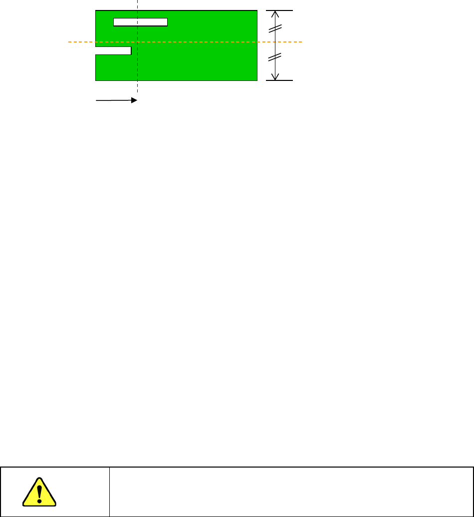
13) Clamp offset (Board whose X-dimension of the “PWB dimensions” exceeds the regulated
size (650 mm))
As the “Clamp Offset,” specify the detection position (Y-coordinate) of the sensor (HMS) that
it to detect a board when the board is fed twice.
* Notes to be applied when you specify the “Clamp Offset”
If the default position satisfies the following conditions, you have to change the
setting of the menu item “Clamp Offset.”
In the 50-mm area from the rear edge of a board
1. there is a “notch” or a “slit” of a board,
2. there is a tall component (3 mm or taller) or a lead of a component or
3. there is a mirrored section or a concave/convex section (for example, when a jig board is
used).
To change the setting, specify the position that does not satisfy the conditions above, is not
near any conveyor rail, and is located within the area whose height can be measured with
the sensor (board transport reference surface ± 10 mm).
(It is recommended to specify a position at which any component is not placed.)
After specifying the offset, check to see if a board can be fed and clamped twice (HMS
clamp) normally by selecting the [Pwb conveyor] command, and then the <Pwb load (2nd)>
button.
14) Head height at production start
Set a height necessary to determine the specifications of the ZA-axis height at production
start. When components are placed on the PWB in the upstream process or when the boss
is protruded from the PWB while components are placed on the back side, set this height.
Additionally, when a tray holder or custom-order unit is always installed in the machine, set
the maximum height among them.
The initial value is blank and the data is not completed with blank. Therefore, it is necessary
to enter the head height at production start when the production program of other model
(without the head height at production start) is loaded.
CAUTION
If the head height at production start is set to a low level, this may cause a
machine crush or component failure. Be sure to enter a correct value after
checking the upstream process of the line or the machine status.
15) Global bad mark
You cannot use this menu item for a single-circuit PWB.
16) Bad mark
You cannot use this menu item for a single-circuit PWB.
Default position (Sensor
detecting line)
Slit
Notch
50mm
Part 1 Basic Operation Chapter 4 Creating a Production Program
4-16
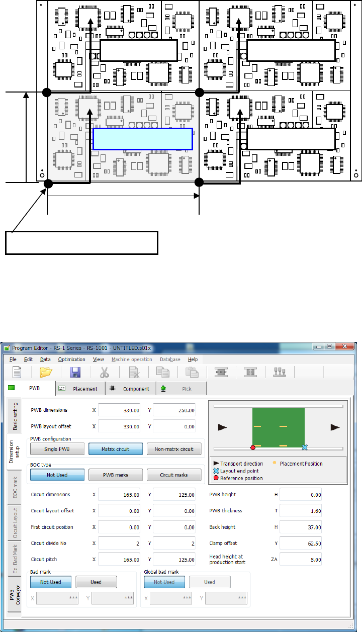
(3) Multi-plane matrix PWB
On a multi-plane PWB, two or more circuits of the same type are arranged.
There are two types of multi-plane PWBs: matrix circuit PWB and non-matrix circuit PWB.
The angles of all circuits are equal to one another, and the distance between two consecutive
circuits (pitch) is equal on a matrix circuit PWB. As Placement data, create data on one circuit
(called as “reference circuit”), as PWB data, enter information on the circuit arrangement (such as
the pitch between circuits and the number of circuits).
Pitch Y
Reference circuit
Fourth circuit
Second circuit
Third circuit
Pitch X
Origin of the reference circuit