RS-1_instruction manual.pdf - 第383页
Part 1 B asic O peration Chapter 4 Cr eating a Produc tion Progra m 4- 48 2) Packaging sty le From the disp l ayed "Pa ckaging style" list , select a c omponent sup ply device. To change it, se lect a packaging…
Part 1 Basic Operation Chapter 4 Creating a Production Program
4-47
4.3.5.2 Creating of component data
The component data creating screen (“Form” screen of the “Component” data screen) consist of
the “Component name” field and the “Comment” field, and seven tab sheets (“Basic setting,”
“Packaging style,” “Centering,” “Pick Condition,” “Place Condition,” “Inspection” and “Vision”).
Component name
The component name used in Placement data is displayed here.
(You cannot edit it.)
Comment
Enter a comment on a component that cannot be distinguished
from other ones just by its name. You can omit the “Comment.”
Up to 127 characters can be entered.
Items you have to set for normal components are displayed on the “Basic setting” tab and the
“Packaging style” tab. Those for components to be recognized with a VCS are displayed on the
“Basic setting” tab, the “Packaging style” tab and the “Vision” tab.
The initial values are registered for other items. Set necessary items only.
Most of recognition errors and other various initial errors after program preparation
can be solved by reviewing the component data. If this is the case, make
adjustment by changing the component height as well as those values set as the
"initial values" described above.
(1) Basic setting
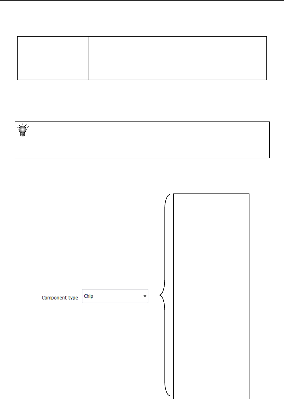
1) Component type
Select a component type from the drop-down list.
Chip
Chip (LED)
Melf
Elec. Cap.
GaAsFET
SOT
SOP
HSOP
SOJ
QFP
QFN
PLCC (QFJ)
PQFP (BQFP)
TSOP
TSOP2
BGA
FBGA
Outline recog.
GNRL Vision
RNA
Trimmer
CONN
CON2
CONZ
CONX
SKT-J
SKT-G
SKT-B
Other
Part 1 Basic Operation Chapter 4 Creating a Production Program
4-48
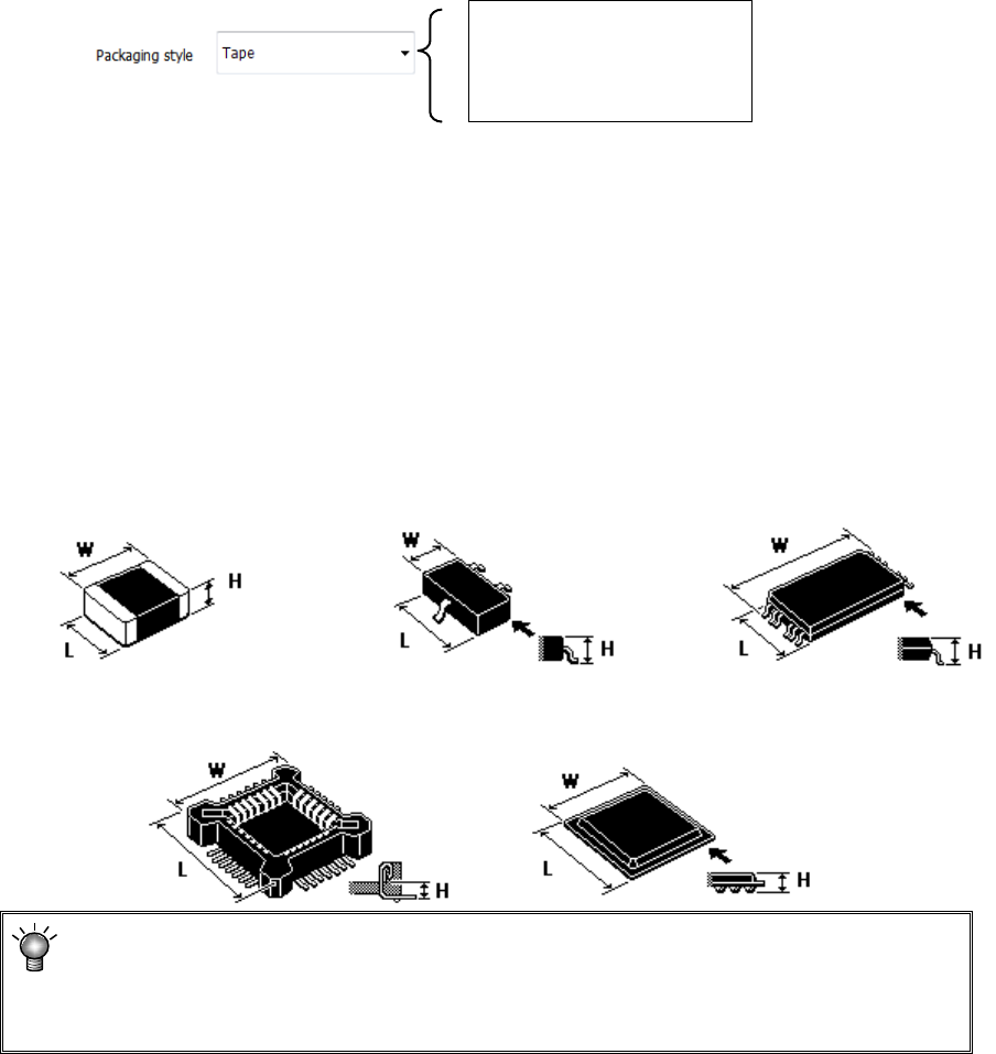
2) Packaging style
From the displayed "Packaging style" list, select a component supply device.
To change it, select a packaging style from the pull-down list.
Tape
Stick
Tray
3) Outer dimensions
Enter outer dimensions of component matched to each component type.
Enter them by referring to the component illustration shown in the lower left part of the form
screen. Note that there are 2 cases, namely, one where the lead is included and the other
where the lead is not included, depending on the component type.
The graphic data based on JUKI component feed angle definition 0° is displayed according
to "Component type."
Example: W = Outer dimension, horizontal
L = Outer dimension, vertical H: Component height
♦ Square chip ♦SOT ♦T-SOP
♦ Socket ♦BGA
If you enter the dimensions oppositely, that is, enter the width (horizontal) to the
“Length” field or vice versa, the system may not be able to center the component.
If a wrong component height is entered, a laser recognition error may be easily
caused by unstable laser measuring position.
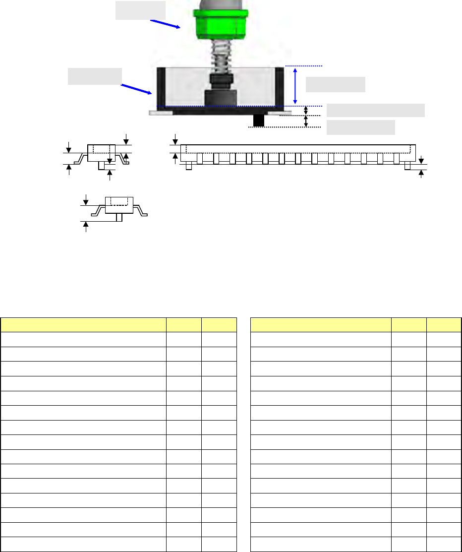
4) Other
① Pick depth
Enter the height from the nozzle pick surface to the top surface of the component. Usually,
the default value is used for operation.
② Boss Height
Enter the boss height (projection height on the bottom surface) of the connector.
Usually, the default value is used for operation.
Component height=Component height measured with laser-Boss height
If the picking surface of the nozzle is located at the lower position than the top surface of the
component, such as connector component, enter the distance from the nozzle tip to the top
surface of the component. In this case, the "Component height" will be the distance from
the nozzle tip to the bottom surface of the component.
Part 1 Basic Operation Chapter 4 Creating a Production Program
4-49
Example:
5) Centering method
Specify the method of obtaining the center of the component.
Select this method according to the component (in consideration of specifications, accuracy,
and tact). However, available centering methods are limited depending on the component
type.
Component type
Laser
Vision
Component type
Laser
Vision
Square chip O O BGA O O
Square chip p (LED) O X FBGA X O
Melf O X Outline-recognized component X O
Elec. Cap. (Aluminum electrolytic capacitor) O O General-purpose vision component X O
GaAsFET O O RNA (Network resistor) O X
SOT O X Trimmer O X
SOP O O One-direction lead connector O O
HSOP O O Two-direction lead connector O O
SOJ O O Z-lead connector O O
QFP O O Expanded-lead connector X O
QFN O O J-lead socket O O
PLCC (QFJ) O O Gull-wing socket O O
PQFP (BQFP) O O Socket with bumper O O
TSOP O O Other O X
TSOP2 O O
Component
height measured
with laser
Component height
Pick depth
Boss height
Boss height
Component height
Pick depth
Nozzle
Boss height
Connector