RS-1_instruction manual.pdf - 第568页
Part 1 B asic O peration Chapter 4 Cr eating a Produc tion Progra m 4- 233 (5) S ingle m easureme nt The system m easures o nly the selected com ponent. 1) Setting the con ditions for S ingle m easureme nt mode When you …
Part 1 Basic Operation Chapter 4 Creating a Production Program
4-232
(4) Actions taken during measurement
1) Head used to pick up a component
The system automatically selects a head used to pick up a component so that a nozzle can
be replaced with another one lest frequently by attempting to use a nozzle already attached
on a head. The system may use a different head every time it measures a component
depending on the nozzle attachment conditions.
2) Return of a component after measurement
This setting decides whether to return a measured component to the previous position or
discard it. Selection is limited depending on the packaging style of a component (see the
table below).
Since a component whose size is 1 mm or less may be placed on its side or turned upside
down when it is returned, the system displays the message so that you can select how to
handle it.
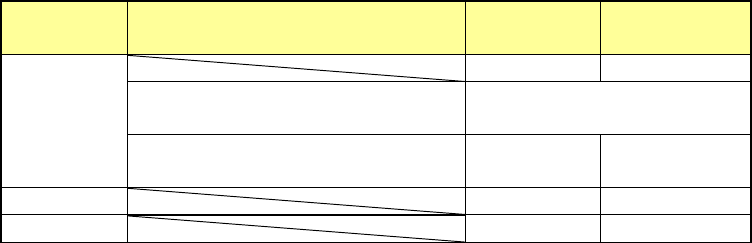
Packaging
style
Condition 2
Returning a
component
Discarding a
component
Tepe
――
○
The shorter side length of the
outer dimensions is 1 mm or less.
Query * 1
The shorter side length of the
outer dimensions is 1 mm or more.
○ ○ *2
Tray
○
○
*2
Stick
―
○
Where to discard a component is determined according to the setting of the menu item
“Component reject to.”
*1 The system displays the dialog box on which you have to select whether to return a
component or discard it. The system displays this dialog box before it starts continuous
measurement of components in Continuous Measurement mode.
*2 When you select the “IC collection belt” or “Protect” for the menu item “Component reject
to,” the system operates according to the corresponding setting.
3) Selecting a feeder which is used to pick up a component
If there are two or more feeders assigned to the same type of component in Pick data, a
component starts being picked up based on the data you entered first as the default setting.
4) Changing the coordinates of a component pick-up position
If the system cannot pick up a component normally, you can manually input a component
pick-up position or teach the coordinates of the pick-up position to change it.
5) Manual component pick-up
If there is no Pick data created, you can manually attach a component to the nozzle. In this
case, any pick-up coordinates are not entered. You cannot operate a feeder either.
Part 1 Basic Operation Chapter 4 Creating a Production Program
4-233
(5) Single measurement
The system measures only the selected component.
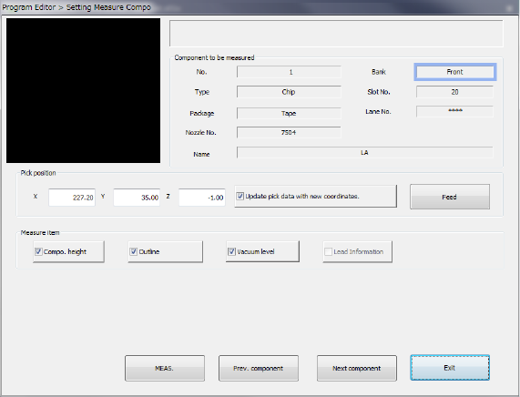
1) Setting the conditions for Single measurement mode
When you select the [Machine operation] command from the Program Editor menu, and
then the [Current component] command, the following screen appears.
① Component to be measured
The descriptions of a component to be measured are displayed here.
② Pick position
The component pick-up position is displayed here. You can change the pick-up position to
the previous or next alternative component. If there is no Pick data created, each menu item
is not displayed. So, you cannot change the component pick-up position, feed the
component, or perform the teaching operation.
• Change of the pick position
If the pick-up position of a component used for measurement is different from the actual
pick-up position, you can teach the coordinates of the component placement position.
You can change the pick-up position by entering it manually without teaching it also.
• Update pick data with new coordinates.
Check this box if you are to save the taught result into Pick data. When unchecked, the
displayed coordinates are used to pick up the current component only.
• <FEED> button
Every time you click this button, the system knocks the feeder once to feed the
component (not available with a 32-mm paper tape).
③ Measure Item
Select the item to be measured. By default, all items that can be measured are selected.
The items that can be measured vary depending on component types.
④ <MEAS.> button
This button measures the current component only.
⑤ <Prev. component> button/<Next component> button
These buttons display the alternate component of the component displayed at the preset if
there is.
⑥ < Exit> button
This button quits measurement of the current component, and returns to the screen from
which you invoked the screen above.
Part 1 Basic Operation Chapter 4 Creating a Production Program
4-234
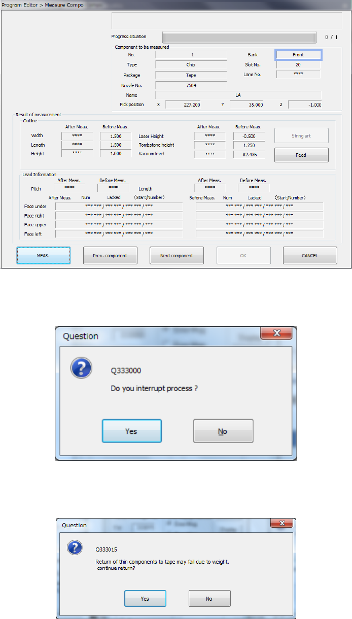
2) Screen displayed while the current component is being measured
(“Measure Compo is being executed” screen)
When the system is measuring the current component, the screen like the one shown below
appears, and it shows that the processing being executed is updated sequentially.
When you press the <STOP> switch, the system aborts measurement, and displays the
following dialog box on the screen.
Select whether to finish measurement or not.
Depending on the packaging style of a component, the dialog box which asks you whether
to return a component to its original position or discard it after measurement, may appear on
the screen if the size of a component is 1 mm or less.