RS-1_instruction manual.pdf - 第584页
Part 1 B asic O peration Chapter 4 Cr eating a Produc tion Progra m 4- 249 (3) Operation of a coplan arity check Create dat a of a product ion program f rom “Com pon ent data” t o “Visi on data,” and then sel ect the [Me…
Part 1 Basic Operation Chapter 4 Creating a Production Program
4-248
4.5.7.4 Coplanarity Inspection (option)
This command runs a coplanarity check.
(1) Coplanarity check system
When you select the commands [Vision Recognize] command and the [Coplanarity Inspection]
command in this order, the machine executes the control process in sequence based on the
values set in Component data, and checks to see if any error does not occur.
(2) Operations to be performed when a coplanarity check is run
1) Head used to pick up a component
A head used to pick up a component is automatically selected.
A nozzle already attached on a head is used in priority to other nozzles so that a nozzle can
be replaced with another one as infrequently as possible.
The machine may use a different nozzle every time it performs measurement depending on
the nozzle attachment conditions.
You can select a head to be checked also
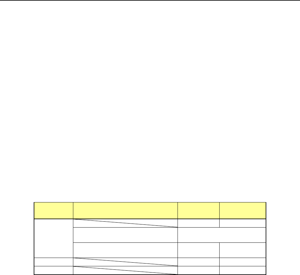
2) Returning a component after a check
The machine returns a checked component to its original position in some cases, and may
discard it in other cases. Which action is to be taken is decided according to the packaging
style of a component as shown in the table below.
Where to discard a component is determined according to the setting of the “Component
reject to” field of the Component data. When the machine returns a component whose size
is 1 mm or less, it may cause a tombstone problem or it may be turned over. Therefore, the
machine displays the “Question” dialog box to ask you which action to be taken.
Packaging
style
Condition 2
Returning a
component
Discarding a
component
Tepe
―
○
The shorter side length of the
outer dimensions is 1 mm or less.
Query * 1
The shorter side length of the
outer dimensions is 1 mm or more.
○ ―
Tray
○
―
Stick
―
○
*1 The system displays the dialog box on which you have to select whether to return a
component or discard it. The system displays this dialog box before it starts continuous
measurement of components in Continuous Measurement mode.
3) Selecting a component supply unit
If two or more component supply units are assigned to the same type of component in Pick
data, a component starts being picked up based on the data you entered first by default.
You can change a component supply unit intentionally also.
4) Changing the coordinates of a component pick-up position
If the system cannot pick up a component normally, you can manually enter a component
pick-up position or teach the coordinates of the pick-up position to change it.
5) Manual pick-up of a component
If there is no Pick data created, you can manually attach a component to the nozzle. In this
case, you cannot enter any pick-up coordinates. You cannot operate a feeder either.
Part 1 Basic Operation Chapter 4 Creating a Production Program
4-249
(3) Operation of a coplanarity check
Create data of a production program from “Component data” to “Vision data,” and then select the
[Meas/Insp] command from the menu, and the [Coplanarity inspection] command on the displayed
menu.
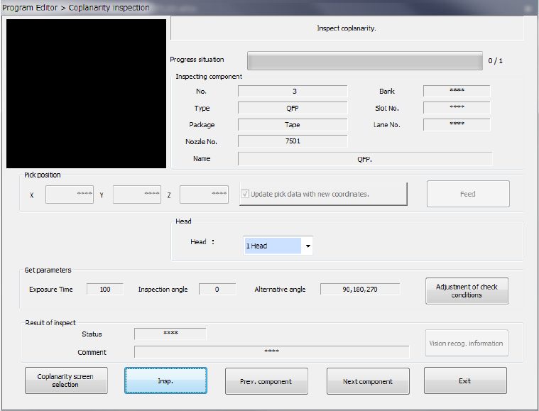
The screen like one shown below appears.
1) Component being inspected
Component data necessary for a coplanarity check is displayed here.
2) Pick position (Pick-up position of a component to be measured)
Data on a position from which a component is picked up is displayed here. You can
change this pick-up position to the pick-up position of the previous alternate component or
that of the next alternate component also. If there is not any Pick data or if an MTC is
specified, each item is dimmed on the screen, so you cannot change the component pick-up
position, knock the feeder, or perform teaching operation.
● Update pick data with new coordinates
Specify whether to update Pick data with the taught result.
When you do not place a checkmark in this check box, the coordinates are applied to the
pick-up operation this time only.
● Feed
This button knocks a feeder to feed components.
3) Head (to be used)
You can select a head to be used for inspection. Select the desired head from the list of the
combo box.
4) Get parameters
When you press the <Adjustment of check conditions> button, the system obtains the
following data that allows the coplanarity inspection: “Exposure time,” “Inspection angle”
and “Alternative angle,” which means the alternative inspection angle.
Part 1 Basic Operation Chapter 4 Creating a Production Program
4-250
5) Result of inspect
The image recognition result or the coplanarity check result is displayed here.
● Status
If the machine measures an object successfully, “OK” is displayed here. Otherwise,
“NG” is displayed.
● Comment
The cause of an error is displayed here.
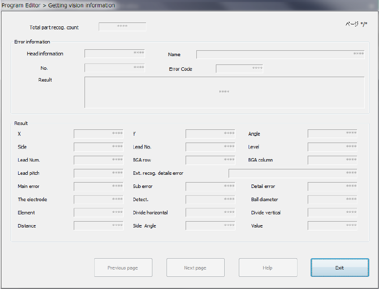
● <Vision recog. information> button
If the image check result is “NG,” this button allows you to display the detailed
information on the error on the screen.
The machine can display the detailed data on the 16th error from the latest one.
The detailed information on image recognition errors is displayed on the screen from the
latest one.
<Previous page> : Displays information on the previous image recognition error.
<Next page> : Displays the next information on the current image recognition error.
<Help> : Displays the Help function appropriate for the image recognition error
displayed currently.
<Exit> : Closes the image recognition error information screen.