RS-1_instruction manual.pdf - 第610页
Part 1 B asic O peration Chapter 4 Cr eating a Produc tion Progra m 4- 275 - When the e lement t ype is “User def i nitio n” ● Operation mode Specify the op eration mode of t he user - defi ned element . - Direction judg…
Part 1 Basic Operation Chapter 4 Creating a Production Program
4-274
Element type Explanation
Lead Element group data consisting of leads is created.
Side Element group data consisting of sides is created.
Corner Element group data consisting of corners is created.
Mark Element group data consisting of marks is created.
Center of gravity Element group data consisting of center of gravity for rough positioning is
created.
User definition Element groups consisting of image data for direction inspection are created.
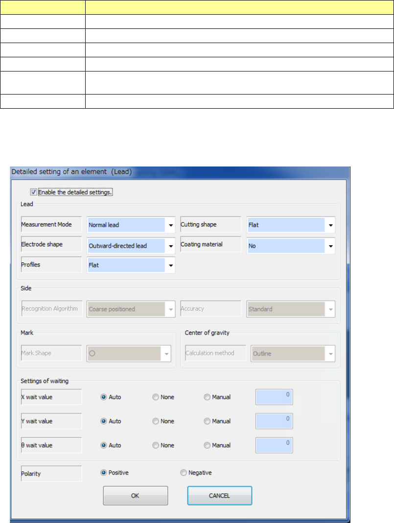
- When the element type is “Lead,” “Side,” “Corner,” “Mark” or “Center of gravity”
See Chapter 6 “General-Purpose Vision Component” for details of the settings.
Part 1 Basic Operation Chapter 4 Creating a Production Program
4-275
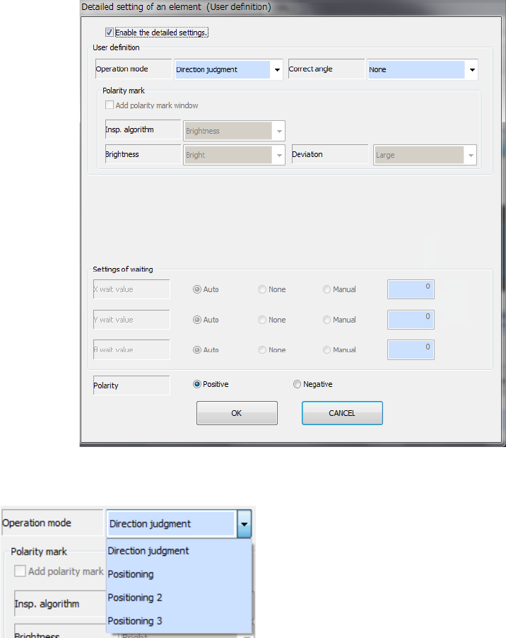
- When the element type is “User definition”
● Operation mode
Specify the operation mode of the user-defined element.
- Direction judgment
Creates the definition for direction judgment only.
You have to create a side element and/or a lead
element for positioning also.
- Positioning
Creates the definition for positioning only: this is for
centering.
You cannot create a side element or a lead element.
- Positioning 2
Creates the definition for positioning and that for direction judgment (one group).
The system determines the direction with the brightness on the window set for editing a
component. Therefore, the system does not memorize the shape. To determine the
direction with the shape, select “Positioning 3.”
- Positioning 3
Creates the definition for positioning and that for direction judgment (one group).
The system determines the direction with the shape set on the window for editing a
component.
You cannot create a side element or a lead element if you select this setting.
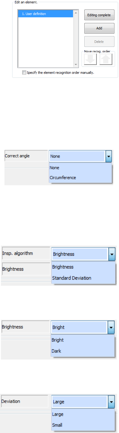
When you select “Positioning,” “Positioning 2” or “Positioning 3” as the “Operation mode,”
you can set up to eight windows for areas to be used for recognition. While you are editing a
user-defined element for positioning, the displayed screen for editing an element is changed.
After selecting an area, select the <Add> button to continue to edit an element or the
<Editing complete> button to finish editing an element.
Part 1 Basic Operation Chapter 4 Creating a Production Program
4-276
* A characteristic point(s) that can be used for recognition is (are) flashing when an area is
selected. If you include many unstable shape portions of a component or many portions not
flashing, the system may recognize an element by mistake in some cases.
● Add polarity mark window
Check off this check box when you are to create the direction judgment definition when you
select “Positioning 2” or “Positioning 3” as the “Operation mode.”
● Correct angle
- None
This is set by default.
- Circumference
Select this when an electrode(s) and/or a mark(s) are arranged on the circumference of a
component. If you select “None” for such a component, the system may recognize an
element by mistake.
● Insp. algorithm
Select this when you select “Positioning 2” as the “Operation mode.”
- Brightness
The system determines the direction by the
brightness.
- Standard Deviation
The system determines the direction by the
variance in density.
● Brightness
Specify this when you select “Positioning 2” as the “Operation mode” and “Brightness” as
the “Insp. algorithm.”
- Bright
Specify this when a bright mark or electrode in
the area for determining the direction.
- Dark
Specify this when a dark mark or electrode in the
area for determining the direction.
● Deviation
Specify this when you select “Positioning 2” as the “Operation mode” and “Standard
Deviation” as the “Insp. algorithm.”
- Large
Specify this when the density difference of the
area for determining the direction is large.
- Small
Specify this when the density difference of the
area for determining the direction is small.