RS-1_instruction manual.pdf - 第782页
Part 2 D etaile d Descript ion of E ach Functi on Chapter 9 M anual Control 9- 10 (2) Control Head Select the he ad to be controlled with t he radio but ton. This selecti on i s not af fected by the setting o f the “ Dev…

Part 2 Detailed Description of Each Function Chapter 9 Manual Control
9-9
Status
Description
0
Indicates that the command was finished.
1
Indicates that the command was normally executed.
11
Indicates that the window at the left end is closed. Check the component position.
12
Indicates that the window at the right end is closed. Check the component position.
13
Indicates that the windows at both ends are closed. Check the component position.
20
An error occurred in communication with LNC120.
21
The communication with LNC120 failed. Check whether LNC120 is correctly
connected. (The IP address may not be set correctly.)
22
A component can be detected on the laser at all times.
The nozzle may be too long or the laser surface may be damaged.
23
No component can be detected by lowering the Z-axis.
25
An error occurred in axis movement during laser measurement.
26
An error occurred during communication with the laser sensor. However, the
communication was restored.
27
An error occurred during communication with the laser sensor. Because the
communication could not be restored, restart the equipment.
28
No shadow could be detected during measurement.
30
An illegal parameter was detected in the command.
31
Illegal data was detected.
32
Laser recognition was not completed.
33
Measurement resulted in an error for other cause.
34
Encoder input error. Check the encoder cable or connector contact.
40
A packet number error was detected in the data received from the laser.
41
A command error was detected in the data received from the laser.
42
An address error was detected in the data received from the laser.
43
A data number error was detected in the data received from the laser.
44
A timeout error occurred in the communication with the laser.
45
A timeout error occurred in receiving data from the laser.
46
A timeout error occurred in sending data to the laser.
47
A retry over error occurred in sending data to the laser.
50
A recognition error occurred in ONCE recognition processing.
51
A sensor error was detected during ONCE recognizing processing.
60
A request to obtain a measurement result was executed though no measurement was
executed.
61
No measurement data could be obtained.
62
A request to obtain a measurement result was executed during measurement rotation.
63
A request to obtain a measurement result was executed during measuring processing.
64
Correct data for measurement could not be obtained.
65
Measurement cannot be performed because the center of rotation to be measured is
out of the center of measurement.
66
Measurement is now interrupted.
67
Sufficient data for measurement could not be obtained.
68
A request to obtain a measurement result was executed during measurement rotation.
(Hold OFF angle)
70
The sensor function was executed unless the laser was not initialized.
71
An unexpected error occurred in the laser.
72
Measuring processing cannot be executed because the set window size is small.
Part 2 Detailed Description of Each Function Chapter 9 Manual Control
9-10
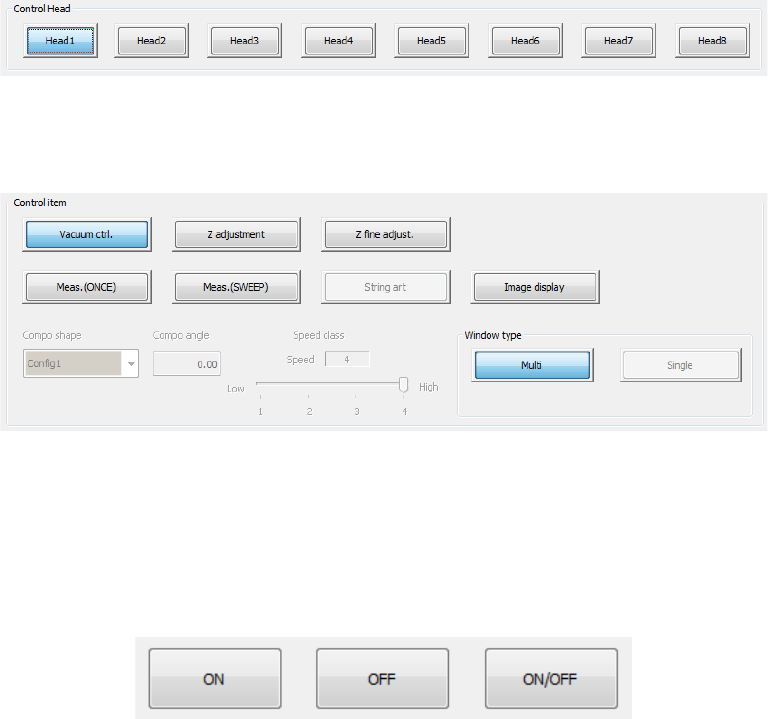
(2) Control Head
Select the head to be controlled with the radio button.
This selection is not affected by the setting of the “Device enable” tab invoked from the
“Machine Setup” screen.
(3) Control item
Select an item to be controlled with the corresponding push button.
An outline of each control will be described later. Refer to “9.3.3.1 Control items: Vacuum
control and later.
(4) Control buttons
Execute control items by using the control buttons in the lower part of the screen.
The control button display varies depending on control items. (* The figure shows an
example.)
Part 2 Detailed Description of Each Function Chapter 9 Manual Control
9-11
9.3.3.1 Control item: Vacuum ctrl.
This button turns ON/OFF the vacuum device of the selected head.
When the control item “Vacuum control” is selected, press the <ON> button, <OFF> button, or
<ON/OFF> button for control.
The displayed pressure is updated when the system finishes controlling the vacuum condition.
9.3.3.2 Control item: Z adjustment
This button controls the Z-axis coordinate of the selected head.
Use this button to pick up a component with a nozzle.
When the control item “Z adjustment” is selected, press he <Up> button, <Down> button, or
<Up/Down> button for control.
The displayed coordinate is updated when the head finishes moving completely.
9.3.3.3 Control item: Z fine adjust.
This button controls the Z-axis coordinate of the selected head.
Use this button to move the picked component to the laser measurement height.
When the control item “Z fine adjust” is selected, press the <Up> button, <Down> button, or
<Up/Down> button for control.
The displayed coordinate is updated when the head finishes moving completely.
9.3.3.4 Control item: Meas. (ONCE)
This button measures the head with laser (ONCE).
“ONCE” is the function for obtaining the information on the shadow shot with the sensor at the
present. The measurement result is displayed in the “Status” table.
When the control item “Meas. (ONCE)” is elected, press the <Exec> button for control. When
you select <LA> button, the head is moved to the end (bottom surface of component when a
component is picked up) of this head.
The measurement result displayed in the “Status” table is updated when the system finishes
measuring.
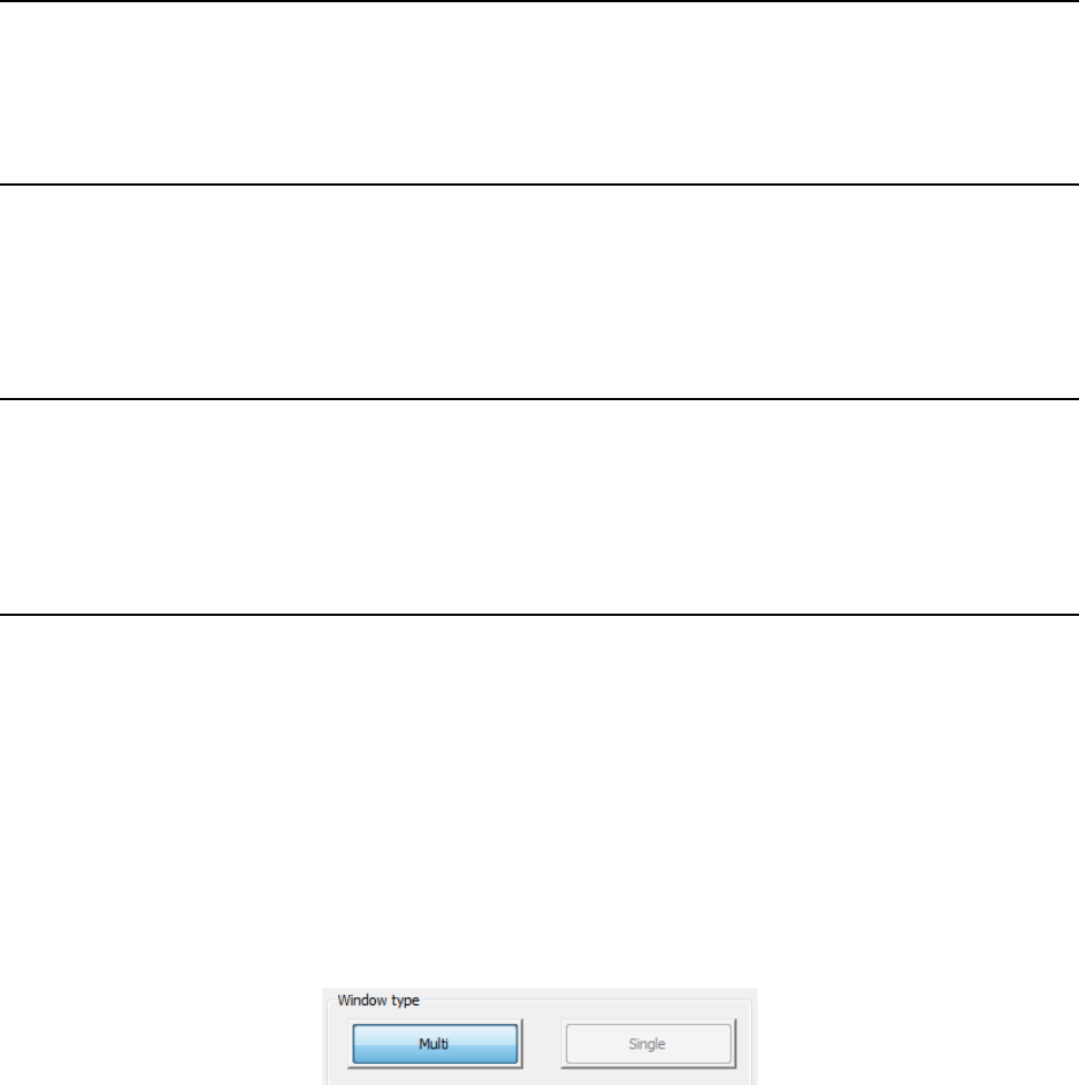
Select the window type to be used during measurement with the corresponding push button
displayed on the right bottom corner of the screen.
When you select other than the control item “Meas. (ONCE)” or “Meas. (SWEEP),” setting is
disabled.
a) Multi
This button sets an area in which two or more heads can measure components at the same
time as the window size.
(Center of the rotation of the nozzle attached on the specified head ±5.5mm)
When you plan to measure a component whose size exceeds this window size, select the
<Single> button.
b) Single
This button sets an area in which the maximum size component can be measured with laser
as the window size.
When you select this button, the system uses the measurement areas (windows) of other
heads also.
Therefore, if another head is moved down to the laser height, the system may fail to
measure a component.
Before measurement, check to see if any other head is not moved down to the laser
measurement height.