RS-1_instruction manual.pdf - 第859页
Pa r t 2 Det ai l ed Des c r i pti on o f Ea c h Fu nc ti on Chapte r 1 1 S el f - diagnosis Func ti on 11 -1 Chap ter 1 1 Se lf- diag nosis Fu nct ion Outline T he sel f - diag nosi s func tion g iv es t he sup p ort of…
Part 2 Detailed Description of Each Function Chapter 10 Machine Management Information
10-45
10.5 Settings
10.5.1 Setup – Operation Information of each nozzle
Refer to “10.3.4 Operation information by nozzle, (3) Exchange frequency setting.”
10.5.2 Setup – Operation Information of each head
Refer to “10.3.5 Operation information by head, (3) Exchange frequency setting.”
10.6 Initialize
10.6.1 Reset
This function is the same as the <Reset> button provided in each screen in 10.4.
10.6.2 Initializing the total device operation results
From the device operation information screen for each device, all the device operation results are
initialized.
(1) Select [Initialize] – [Initialize total device operation results] in the main menu.
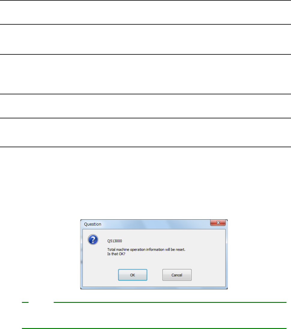
(2) A question message to check total initialization is displayed.
For total initialization, press <OK>.
To cancel a total initialize operation, press <CANCEL>.
[Initialize total device operation information data] permits resetting not only the device operation
information on the screen to be operated but also the operation information of all devices.
Note
Part 2 Detailed Description of Each Function Chapter 11 Self-diagnosis Function
11-1
Chapter 11 Self-diagnosis Function
Outline
The self-diagnosis function gives the support of routine maintenance and preventive maintenance
and an operation record control function for process audit and serviceman’s patrol inspection to
the user.
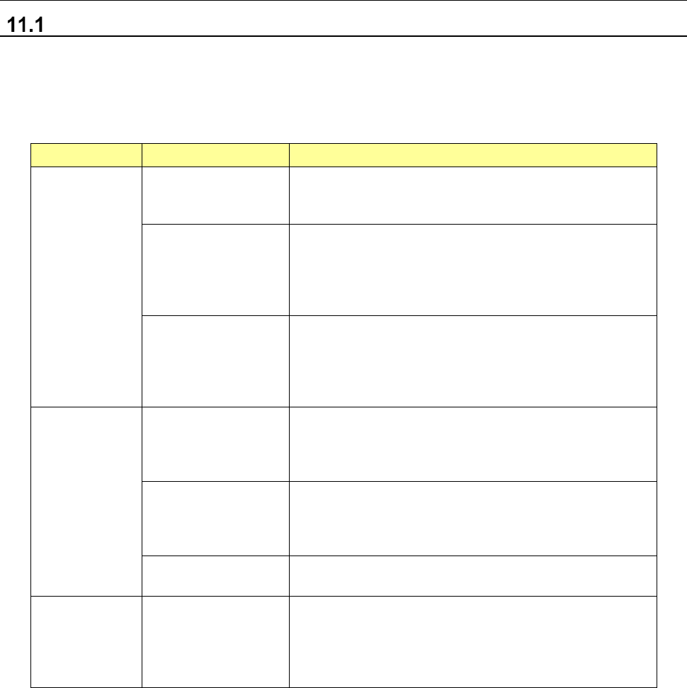
An outline of the functions to be given by the self-diagnosis is shown below.
Item
Sub-item
Description
Display
function
Regular display part
When a component change is required as a result of a
self-diagnosis, a component change notice is made on
the regular display part of the operation screen.
Outline display part
Units are displayed by icons in the maintenance display
part provided in the desktop screen. The icon of a unit
requiring a component change is put in a warning
display status, so that the device status can be known at
a glance.
Detailed display of
replacement
components
The details of a replacement component can be
displayed. When the user opens the detailed display,
the component to be changed can be specified. On the
detailed display, the part number of the replacement
component is also displayed.
Check function
Consumable
component change
notifying function
This function permits grasping the using status of
consumable components and notifying the user that the
replacement must be executed according to each
replacement standard.
Error occurrence
frequency monitoring
function
The error occurrence frequency is monitored. If an
error related to the same portion occurs very frequently,
this function notifies the user that the component must
be replaced.
Individual check
function
A check operation is executed for each operation item
and its result is displayed.
Record saving
function
Check record file
saving
The record of a self-diagnosis is saved in a file. The
record for each month is saved in a single file. The file
is a CSV type text file. The file is surely saved in the
SSD of the main unit and can also be saved in a folder
specified by user.
Part 2 Detailed Description of Each Function Chapter 11 Self-diagnosis Function
11-2
Display Function
Regular display
When there are some replacement components in the whole system for which a routine check is
not yet executed as self-diagnosis information, the maintenance button of the desktop changes
into a red display so that the user can check at all times whether self-diagnosis information exists
or not.
When you press this button, a detailed list of self-diagnosis information in the whole system is
displayed.
The category in which there is self-diagnosis information is displayed with priority.
Even if this button is pressed during production, a detailed list is not displayed.
Furthermore, while an error message is displayed, a return-to-origin is made, or the teaching
screen is displayed, this list is not displayed.
The screens for which this button is effective are shown below.
- Desktop screen (application management)
- Production (production conditions and temporary stop)
- Manual control (main screen)
- Setup (main screen)
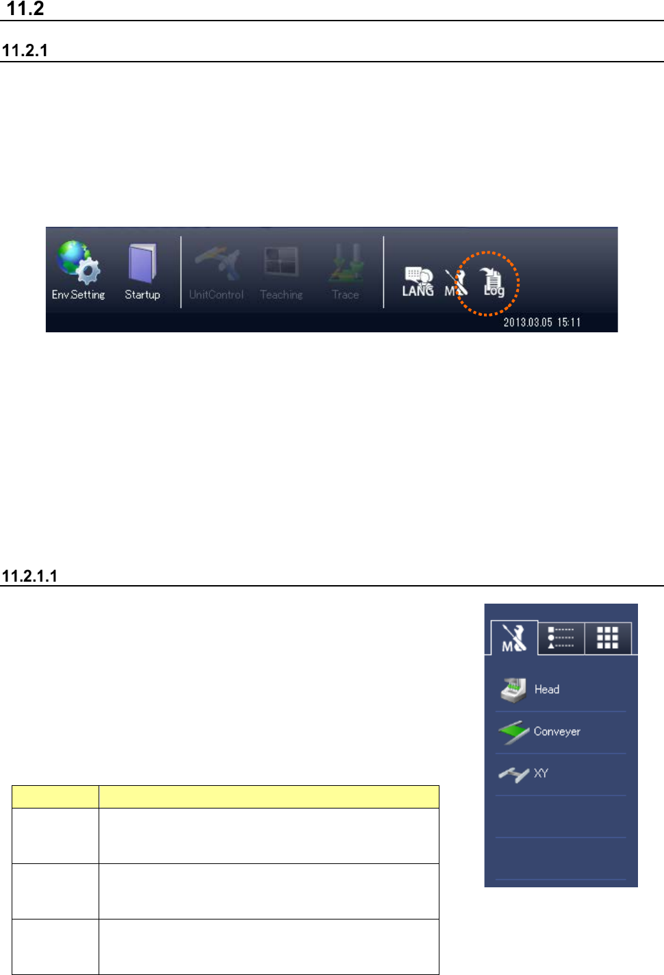
Outline display
If there is replacement component information for each unit, the
button for each unit is displayed in red. If there is any periodic
check item that is not yet executed, the periodic check button is
displayed in red.
When you press the button for each unit, the detailed list of
replacement component information for each unit is displayed.
When you press the periodic check button, the periodic check list is
displayed.
Button
Operation
Head
Displays the replacement component information
related
to the head unit (Z, theta motor, filter, etc.).
Conveyor
Displays the replacement component information
related
to the conveyor unit (conveyor motor, belt, etc.)
XY
Displays the replacement component information
related
to XY unit (XY motor, robot cable, etc.).