RS-1_instruction manual.pdf - 第914页
Part 2 D etaile d Descript ion of E ach Functi on Chapter 12 Handling th e Optional Device s 12 - 30 12.4.4 Operation (1) T e achi ng Fix the IC collection b elt on the f eeder bank, and teach the c oordinat es of the IC…
Part 2 Detailed Description of Each Function Chapter 12 Handling the Optional Devices
12-29
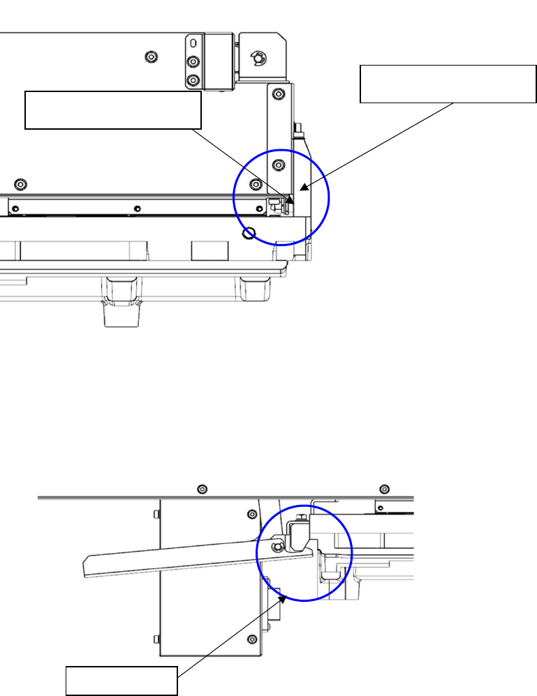
(3) Insert IC collection belt, When the guide pin strikes the bank abutment surface, release the
lever, and lock it with the lock holder.
Note) Check to see if IC collection belt is locked with the lock holder.
(4) Detach it with the reverse procedures of the above.
Bank abutment surface
Guide pin
Lock holder
Part 2 Detailed Description of Each Function Chapter 12 Handling the Optional Devices
12-30
12.4.4 Operation
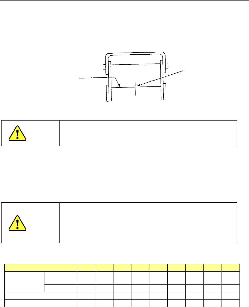
(1) Teaching
Fix the IC collection belt on the feeder bank, and teach the coordinates of the IC
collection belt position which is selected on the Machine setup menu.
Teaching position
CAUTION
To avoid a risk of injury, do not place your hand in the machine, nor
move your face or head close to the machine during operation of the
HOD.
(2) Basic operation
The head of the main unit places an IC on the belt, and the component sensor detects it.
After 0.5 seconds, the IC is fed over the belt at the pitch you set.
- If the belt gets full of ICs and stops, press the Reset switch to restart the machine after
removing ICs from the belt.
CAUTION
- To prevent your body from injury and to avoid damage to the
machine, check to see if the machine main unit stops completely
before opening the safety cover to remove a component from the IC
collection belt.
- If you remove components from the IC collection belt still attached on
the feeder bank, always keep in close touch with other operators.
Number of ICs which can be collected and the feeding pitch set with the rotary switch No.
Switch No. to be set
1
2
3
4
5
6
7
8
9
IC size (mm)
Equal or less
than
10 15 20 25 30 35 40 45 50
Over
−
10
15
20
25
30
35
40
45
Belt feeding pitch (mm)
15
20
25
30
35
40
45
50
55
Maximum number of ICs
31
23
19
16
13
12
10
9
9
Optical axis
Teach the center of the belt
on the component sensor
optical axis.
Part 2 Detailed Description of Each Function Chapter 12 Handling the Optional Devices
12-31
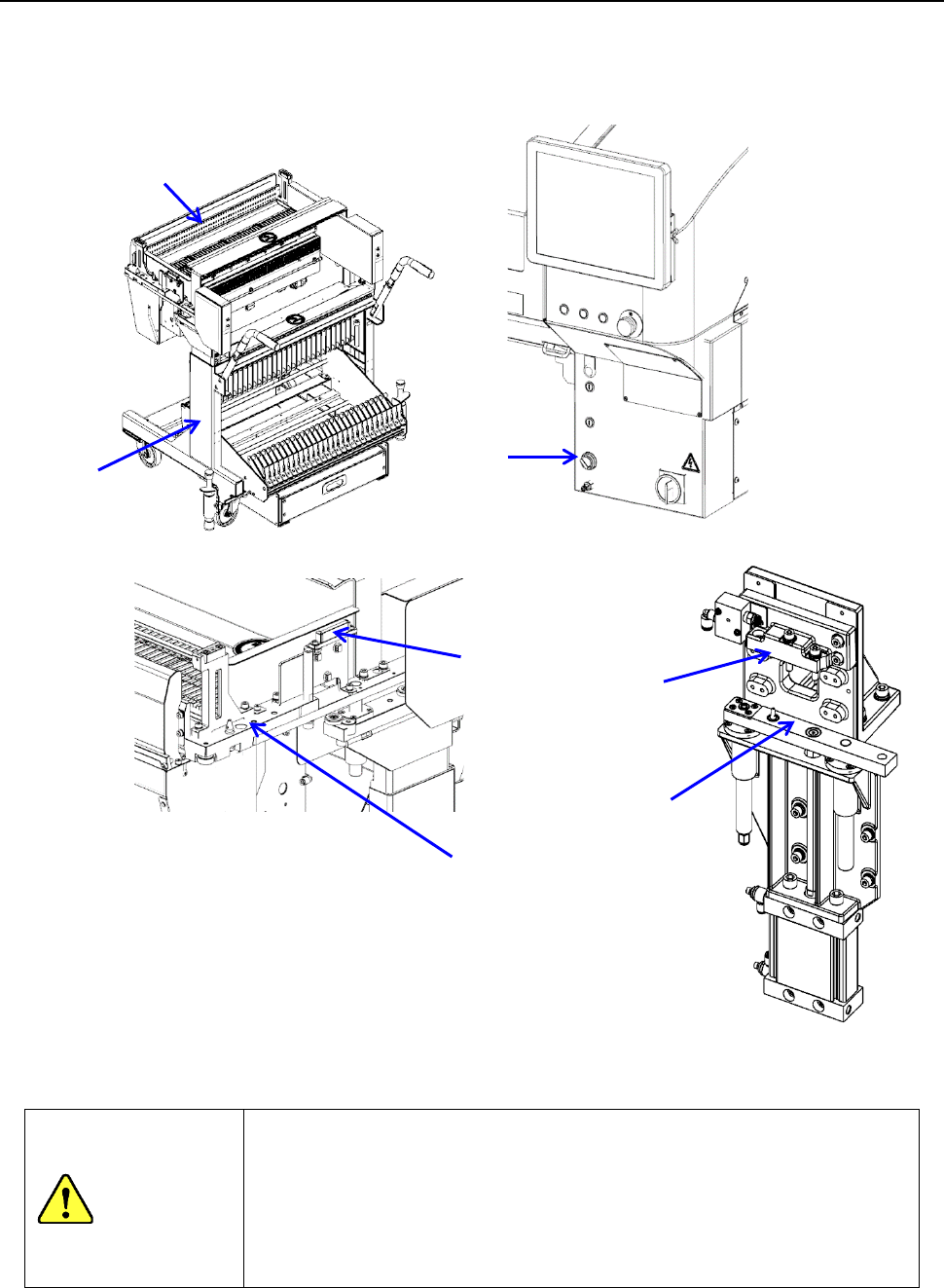
12.5 Feeder exchange trolley for an electric feeder
Since this trolley allows feeders to be attached/detached to/from the main unit all at once and/or
allows you to set up a feeder prepared for the next production during production, it can shorten the
setup time, and makes the setup of the conveyor easier too.
Two types of feeder exchange trollies are provided for each bank type: RF bank and EF/RF bank.
CAUITON
Check to see if there is no substance such as a component on parts that
come in contact with the machine main unit such as the “electric bank 2
(topside),” “bank lifter 4,” “bank support 5” and “bank connector 6.” If there
is any substance on such a part, it interferes with the machine when the
bank moves up, and this may damage not only the substance itself but also
the machine and the connector, and then may cause a fire due to
short-circuiting caused by such a damage.
①
Feeder exchange trolley main unit for an electric feeder
② Electric bank
③ Bank switch
④ Bank lifer
⑤ Bank support
⑥
Bank connector
②
①
③
④
⑤
⑥
② (Topside)